


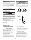
To reduce the risk of electric shock, your garage door
opener has a grounding type plug with a third grounding
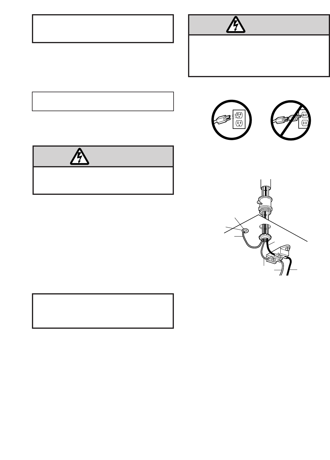
pin. This plug will only fit into a grounding type outlet.
If the plug doesn't fit into the outlet you have, contact a
qualified electrician to install the proper outlet.
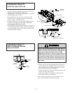
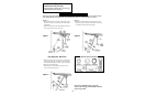
If permanent wiring is required by your local code,
refer to the following procedure:
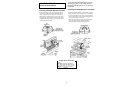
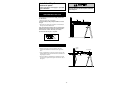
Right
Wrong
Ground Tab
Green
Ground Screw
Ground Wire
BlackWire
Permanent Wiring
Connection
White Wire
Black
Wire
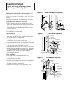
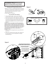
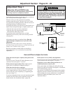
Installation Step 8
Electrical Requirements
To make a permanent connection through the 7/8" diam.
hole in the top of the opener (according to local code):
• Remove the opener cover screws and set the cover aside.
• Remove the attached 3-prong cord.
• Connect the black (line) wire to the screw on the brass
terminal; the white (neutral) wire to the screw on the
silver terminal; and the ground wire to the green
ground screw. The opener must be grounded.
• Reinstall the cover.
18
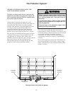
To prevent electrocution or fire,
installation and wiring
must be in compliance with local electrical and building
codes.
Do NOT use an extension cord, 2-wire adapter, or change
the plug in any way to make it fit your outlet.
To avoid installation difficulties,
do not run the opener until Step 9 below.
To prevent electrocution,
remove power from the
garage door opener
and
from the circuit you plan to
use for the permanent connection.
WARNING
WARNING
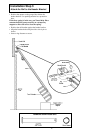
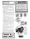
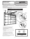
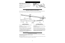
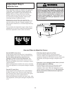
Aligning the Safety Sensors
• Plug in the opener. The indicator lights in both the
sending and receiving eyes will glow steadily if wiring
connections and alignment are correct.
The sending eye orange indicator light will glow
regardless of alignment or obstruction. If the green
indicator light in the receiving eye is off, dim, or
flickering (and the invisible light beam path is not
obstructed), alignment is required.
• Loosen the sending eye wing nut and re-adjust, aiming
directly at the receiving eye. Lock in place.
• Loosen the receiving eye wing nut and adjust sensor
vertically and/or horizontally until it receives the
sender’s beam. When the green indicator light glows
steadily, tighten the wing nut.
Trouble Shooting
1. If the sending eye indicator light does not glow
steadily after installation, check for:
• Electric power to the opener.
• A short in the white or white/black wires. These can
occur under staples or at screw terminal connections.
• Incorrect wiring between sensors and opener.
• A broken wire.
2. If the sending eye indicator light glows steadily but the
receiving eye indicator light doesn't:
• Check alignment.
• Check for an open wire to the receiving eye.
3. If the receiving eye indicator light is dim, realign
either sensor.
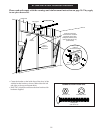
NOTE: When the invisible beam path is obstructed or
misaligned while the door is closing, the door will
reverse. If the door is already open, it will not close. The
opener lights will flash 10 times. (If bulbs are not
installed, 10 clicks are audible.) See page 12.
Installation Step 9
Complete Safety Reversing Sensor
Installation