


10
20002538
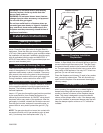
Check the inlet pressure to the appliance, to ensure that
it is as shown in the table on page 3. The minimum is
for the purpose of input adjustment.
The pressure is controlled by the regulator and should
be checked at the pressure test point located in the
control valve body. Access to the pressure test point is
obtained by removing all logs.
The pressure should be checked with the appliance
burning and the control set on ‘HIGH’.
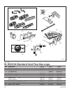
The pressure is preset and locked to avoid tampering. If
the pressure is not as specified, replace the valve. See
Replacement Parts, page 17.
After measuring the pressure, replace the test point
plug, ensure there are no leaks, then place the logs in
their specified positions.
There is a possibility of odor fade in LP. Never
install an LP appliance or service line below
grade without a gas detector.
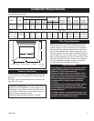
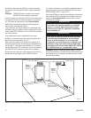
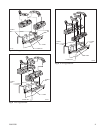
Clearances
(Refer to Fig. 6, Page 9)
To ensure the safe installation into a masonry or factory
built fireplace, the following instructions must be care
-
fully observed.
1. Sidewall Clearances: The clearance from the inside
of the front opening of the fireplace to any combustible
wall or mantel should not be less than 4¹⁄₂”. (Fig. 6a)
2. Ceiling Clearances: The ceiling height should not be
less than 42” from the top of the fireplace opening.
(Fig. 6a)
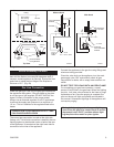
3. Mantel Clearances:
WITHOUT HOOD
If no hood is installed then there must be noncombusti-
ble material from the top front opening of the fireplace to
a height of at least 20” and the full width of the fireplace.
A combustible flat mantel shelf can be no closer than
38¹⁄₂” from the top front of the opening of the fireplace.
(Fig. 6b)
WITH HOOD
If a hood is installed there must be noncombustible
material from the top front opening of the fireplace to
a height of 6³⁄₄” and the full width of the fireplace. A
combustible flat mantel shelf and breastplate may be
installed. (Fig. 6c)
Failure to use a noncombustible material above the
opening as specified in these instructions may cause
damage to the materials used or cause a fire hazard.
4. Grate Clearances: The minimum clearance between
the front legs of the grate and front edge of the fireplace
is 3¹⁄₄”. (Fig. 6b)
NOTE: Combustible mantels, surrounds and cabinets
should be finished with materials that can withstand
250°F.
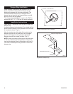
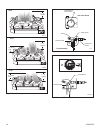
Positioning the Logs
The logs must be positioned on the grate and locating
pins as shown in Figures 7-9.
Gas logs must be properly positioned or the appliance
will not function properly and may result in soot accu-
mulation on the inside of the firebox and/or gas logs.
Make sure there is no flame impingement on the logs
which could result in excessive carbon monoxide emis-
sions.
WARNING: Failure to position the parts in accor-
dance with these diagrams or failure to use only
parts specifically approved with this heater may
result in property damage or personal injury.
Carefully position the logs as shown in Figures 7-9.
Make sure each bottom log engages the locator pins on
the grate and top logs are properly positioned in notch-
es on top of the bottom logs.
Make sure there is no flame impingement on the
cross logs which could result in excessive carbon
monoxide emissions.
The optional volcanic rock may be applied to the
hearth around the burner assembly.
Never place any other material on the burner.
Fireplace Screen
The fireplace screen must be in place when the appli-
ance is operating, and unless other provisions for com-
bustion air are made, the screen must have openings
for the introduction of combustion air.