


5
Vermont Castings VCBVTN/TP & VCPVTN/TP Room Heater
This appliance may be installed in an aftermarket*
manufactured (mobile) home, where not prohibited by
state or local codes.
*Aftermarket: Completion of sale, not for purpose of
resale from manufacturer.
This appliance is only for use with the type of gas
indicated on the rating plate. This appliance is not
convertible for use with other gases.
CAUTION: If you install the heater in a home garage:
• Heater must be at least 18” above floor
• Locate heater where moving vehicle will not hit it.
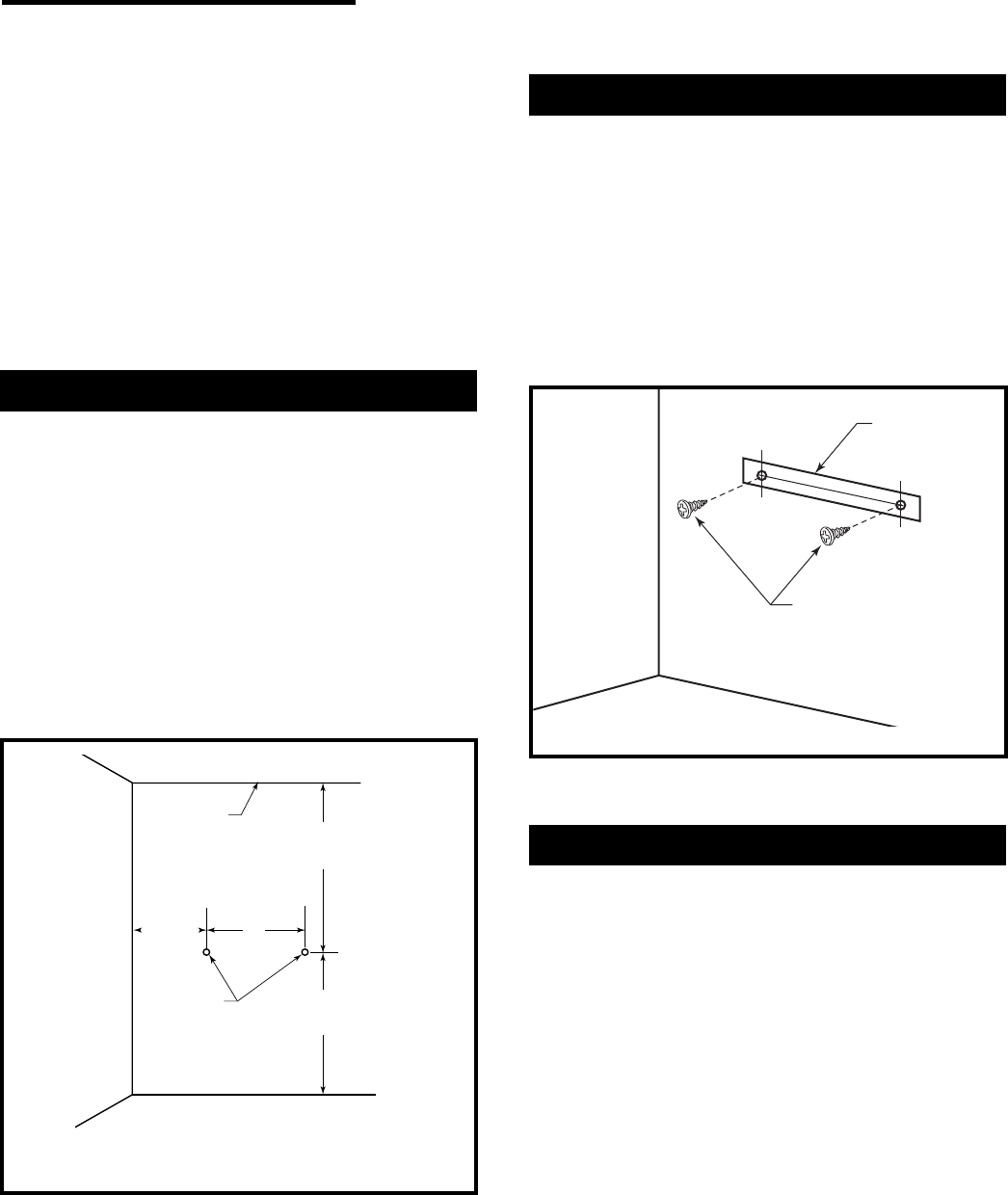
Attach Mounting Screws to Wall
NOTE: Wall anchors and mounting screws are in
hardware package provided with heater.
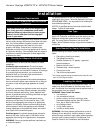
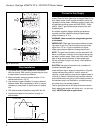
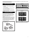
1. Install mounting screws on wall as shown in Figure
3. Use enclosed “paper template” for proper location
of holes. Be sure template is level. It may be neces-
sary to use plastic or lead anchors for plaster walls.
2. Drill holes at marked locations using 9/64” drill bit.
Insert mounting screw.
3. Leave screw head out from wall far enough to attach
heater.
Preparing for Installation
1. Remove heater from carton.
2. Remove all protective packaging applied to heater
for shipment.
3. Check heater for any shipping damage. If heater is
damaged, promptly inform dealer/distributor.
4. Select a location for the heater that will provide
maximum exposure of the radiant surface to the
room, but will not be subjected to accidental contact.
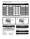
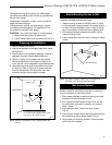
5. Adequate clearance must be available around the
air opening. Refer to Figure 2 for clearances that
must be maintained to the side walls, floor and
horizontal surface surrounding the heater.
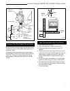
Wall Anchor Method
When mounting heater to hollow walls (wall areas
between studs) or solid walls (concrete or masonry), it
may be necessary to use wall anchors.
1. Place paper template on wall maintaining minimum
clearance. Be sure template is level.
2. Drill holes at marked locations using 5/16” drill bit.
For solid walls, concrete or masonry, drill holes at
least 1” deep.
3. Insert plastic anchor. Tap anchor flush to wall.
(Fig. 4)
4. Insert screw into wall anchor leaving screw head out
far enough from wall to attach heater. (Fig. 4)
5. Hang heater on mounting screws in holes provided
at the rear of the heater.
13"
(330
mm)
Min.
A
20"
(508
mm)
Min.
A = 21
1
/
4
" (330 mm) @ 30,000 Btu/
hr Model
13
11
/
16
" (347 mm) @ 18,000/20,000 Btu/
hr Model
9
7
/
8
" (251 mm) @ 10,000 Btu/
hr Model
36"
(914
mm)
Min.
Ceiling
Adjacent Wall
Screw
Holes
RH110
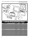
Fig. 2 Minimum clearances to floor, adjacent walls and
ceiling.
Mounting Screws
RH101
Fig. 3 Use paper template supplied to mark location of
mounting holes. Be sure template is level.
Template