


14
STR/CVR Series Woodburning Fireplaces
7412961
WARNING: DO NOT PACK REQUIRED AIR SPACES
WITH INSULATION OR OTHER MATERIALS.
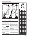
Mark an outline of the roof hole around the center of the
point nail. NOTE: Hole dimensions given in the chim-
ney top installation instructions are horizontal dimen-
sions; therefore, the hole size must be marked on the
roof accordingly.
Cover the opening of the installed chimney so debris
cannot get into the system.
Cut and frame the hole. It is good practice to use fram-
ing lumber that is the same size as the rafters. Install
the frame securely because the chimney top and flash-
ing anchored to the frame must be able to withstand
heavy winds.
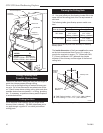
Install Remainder of Chimney Sections
Since you have already preplanned the height of your
termination according to the Ten Foot Rule, continue to
install pipe to the predetermined height.
Check the chimney top installation instructions for
details on how high above the roof top the chimney sec-
tions (all pipes) should extend.
Installing Top Housing or Termination
Follow the installation instructions provided with the
chimney termination you have selected.
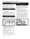
Installing Chimney In a Chase
Refer to Page 5, Figure 4 for an illustration of a typical
chase installation.
CAUTION: Treatment of firestop spacers and construc-
tion of chase may vary with type of building. These
instructions are not a substitute for local building codes.
You must check your local building codes to determine
specific requirements for your city or state. NOTE:
Other building materials may be required in addition to
Firestop Spacers.
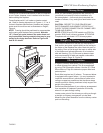
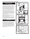
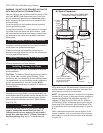
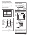
Finishing
CAUTION: All joints between the finished wall and the
fireplace surround (top/sides) must be sealed with non-
combustible material to prevent cold air leakage into the
room. Only noncombustible material may be applied
to the facing of the fireplace surround. (Black painted
area) (Fig. 20)
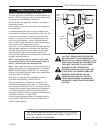
Finish Wall
Finish the wall with material of your choice. Do not
install a combustible mantel shelf less than 12"
(305mm) above the front opening. Do not install a
mantel face plate less than 6" (159mm) from top of
fireplace opening. (Fig. 21) If a combustible mate-
rial is used below a flat mantel shelf, consult your local
building codes for minimum clearance from top of fire-
place opening to bottom of mantel shelf.
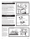
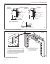
NOTE: No side wall protection is required for fireplaces
installed at 45° to two (2) side walls (corner installation).
Adjacent combustible side walls that are within 16"
(406mm) (STR33/36 and CVR36) and 20" (508mm)
(STR42 and CVR42) of fireplace opening must be pro-
tected with CFM Corporation Wall Shield Model SP40
or a specifically built wall shield described in Figure 20
& 24.
Often a decorative surround or vertical portion of the
mantel is desired. If this is constructed of any combus-
tible material, it must be within the safe zone indicated
in Figure 24.
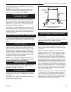
FP717
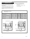
Fig. 20 Minimum clearances to combustibles.
Front View
Side View
Standoff
Combustible framing material MUST NOT
penetrate AIR SPACE (shaded areas).
Air Space Clearances
Only noncombustible
material may be applied
as facing to the black
fireplace surround.
Wall
Shield
Hearth
Extension
0" Clearance
to Floor
Firestop
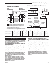
OUTER
DOME
" (13mm)
Air Space
to Sides
" (13mm) air space
to sides
FP717
STR/CVR
AIR SPACES
9/23/98
1" (38mm)
1"
(51mm)
Maintain
" (13mm)
air space
to sides