


17
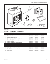
STR/CVR Series Woodburning Fireplaces
7412961
WARNING: HEARTH EXTENSION MUST BE IN-
STALLED IN ACCORDANCE WITH FIGURES 24 AND
25.
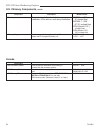
Alternate noncombustible materials may be used
providing the (total) thermal resistance (Rt value) of the
alternate material employed is greater than or equal to
R = 1.09. Thermal resistance (R) or thermal conductivity
(K), may be obtained from manufacturer of the material.
Factors are related by the formula K = 1/R.
T = given thickness
R = thermal resistance for a given thickness (T)
K = thermal conductivity
Noncombustible material with a lower R value may
be used, provided thickness of material is sufficiently
greater to maintain an equivalent (total) thermal resis-
tance (Rt).
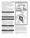
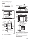
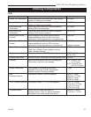
Hearth Installation
A hearth extension is required to protect a combustible
floor in front of the fireplace. Refer to Figure 24 for mini-
mum dimensions and mounting detail.
Note: Hearth Extension must not cover the air inlet
opening of a fireplace.
The hearth extension described in Figure 24 must be a
durable noncombustible material with a minimum (total)
Rt value of 1.09; refer to Figure 25 for examples. The
overall height (above a combustible floor), depth and
width must be as indicated, with the extension centered
to the fireplace opening.
The top of the insulation material must be covered with
a noncombustible decorative covering or a piece of
.018” minimum sheet metal, to protect hearth extension
material. (Fig. 24)
Secure the hearth extension to the floor to prevent
shifting, using trim molding or other similar means at
three (3) outer edges. Seal crack between the fireplace
hearth and hearth extension with a noncombustible
material. (Figs. 24 and 26)
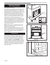
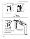
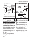
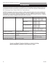
Minimum Wall Clearances
WITH
Noncombustible
Surround Facing
WITHOUT
Noncombustible
Surround Facing
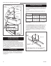
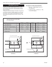
Minimum Hearth Extension Dimensions
(for On-Site Construction)
G
H
G
J
Seal cracks
between the
fireplace
and hearth
extension with
noncombustible
material
Safety strips
must overlap
" minimum
May install
noncombustible
decorative
covering
OR .018" min.
sheet metal
Fireplace
Hearth
Combustible
Floor
Minimum
Insulation
Value "R"
4" MIN.
FP714
STR/CVR
6/4/98
Firebox
Opening
A - Min. clearance
to combustible
perpendicular wall
B - Min. clearance
to combustible
perpendicular wall when
using noncombustible wall shield*
Side
Wall
Side
Wall
F**
C**
E
E
D
4" BRICK
(Example material)
Combustible material permitted within shaded area.
*
Noncombustible wall shield requires 1" CFM Corporation
EH2416 insulation (minimum R Value = 1.85) between
decorative noncombustible rigid covering and combustible wall.
Minimum height and width is 40" x 40".
**
Dimension/degree of angle will vary depending on thickness
of noncombustible surround facing.
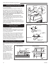
G
H
G
J
CVR
STR
4"
Shaded area starts
1/2" away from
edge of unit
A B C D E F G H J K
STR33/36 CVR36 16" 12" 48° 41° 18" 14" 8" 16" 48" 24"
(406mm) (305mm) (457mm) (356mm) (203mm) (406mm) (1219mm) (610mm)
STR42 CVR42 20" 12" 42° 35° 18" 14' 12" 20" 61¹⁄₂" 24"
(508mm) (305mm) (457mm) (356mm) (305mm) (508mm) (1562mm) (610mm)
FP714
Fig. 24 Combustible side wall protection and hearth extension dimensions.