


3
20012973
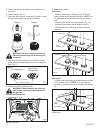
• Remove pilot orifice with needlenose pliers. (Fig.
12) NOTE: Use a wrench to hold pilot tube in place
while removing the orifice.
• Install the conversion orifice.
• Reinstall pilot hood and tighten until mark on pilot
hood aligns with mark on pilot bracket.
CO144
RF Pilot conversion
6/07 djt
Pilot
Orifice
CO144
Fig. 12 Remove pilot orifice.
Burner Orifice Conversion
1. Remove three (3) 3/8” nuts on bottom side of burner
pan. (Fig. 13)
Remove Nuts
Remove Nut
Bottom View
Fig. 13 Remove three (3) nuts securing ember bed in place.
ST918
Pem Studs
ST919
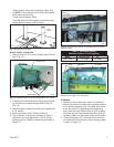
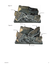
Fig. 14 Tilt ember bed slightly to correctly place on venturi
and air shutter.
Orifice
Bracket
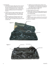
2. Carefully remove ember bed by tilting the right side
up and lifting out toward the right side of the unit.
(Fig. 14)
3. Remove injector orifice from left burner bracket with
a 1/2” wrench.
4. Install conversion orifice. (Refer to Table 2)
5. The air shutter is factory set according to Table 1
and should not need adjustment. The air shutter
opening may be verified by measuring as shown in
Figure 15.
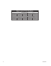
Table 1. Air Shutter Setting
Minimum injector air inlet opening
Model Natural Gas LP
Direct Vent 1/2” Open 1/2” Open
Orifice
Bracket
Orifice
Air Shutter
CO142
Fig. 15 The air shutter setting is 1/2” (13 mm) from the orifice
bracket to the edge of the air shutter.
All Models
1. Replace burner making sure venturi on bottom of
ember bed aligns with orifice and is seated properly
on air shutter assembly. (Fig. 14) Make sure burner
is slid into place at a slight angle and opposite to
how it was removed. When burner is slid into place,
the three (3) pem studs should slide down through
clearance holes into the bottom of the control panel.
2. Thread and tighten 3/8” nuts back onto pem studs
on underneath side of control panel, reversing Step
1 shown in Figure 13.