


17
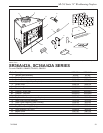
SR/SC Series "A" Woodburning Fireplace
7412948
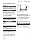
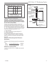
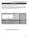
COMMON MATERIALS AND FACTORS
MATERIAL K*
R
MINIMUM
THICKNESS
EH2416
Common Brick
0.458
5.0
1.09 0.50 in.**
0.10 5.46 in.**
(CFM Corporation)
R Value is for Z\x inch.
* Units of K = BTU/SQ FT/HR/˚F/IN
** Thickness of Listed Material
FP533ADD
Addendum
6/1/99 djt
8/4/99 changed .2 to .1
one inch to 1/2 inch djt
FP533ADD
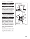
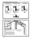
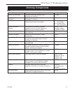
WARNING: HEARTH EXTENSION MUST BE IN-
STALLED IN ACCORDANCE WITH FIGURE 23 AND
MUST NOT COVER THE BOTTOM FRONT OPENING
OF THE CIRCULATING MODEL.
Alternate noncombustible materials may be used
providing the (total) thermal resistance (Rt value) of the
alternate material employed is greater than or equal to
R = 1.09. Thermal resistance (R) or thermal conductivity
(K), may be obtained from manufacturer of the material.
Factors are related by the formula K = 1/R.
T = given thickness
R = thermal resistance for a given thickness (T)
K = thermal conductivity
Noncombustible material with a lower R value may
be used, provided thickness of material is sufficiently
greater to maintain an equivalent (total) thermal resis-
tance (Rt).
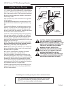
Example of Determining Hearth Extension
Equivalents
To determine the thickness required for any new mate-
rial:
Example for Common Brick
T (new) = 5.0/0.458 x 0.50 in. = 5.46 in. (new required
thickness).
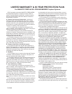
Fig. 24 Hearth extension material factors.
FP550
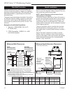
Fig. 25 Sealing gaps.
FP550
BR/BC - SEALING
DETAILS
9/29/97
Wall Covering
Noncombus-
tible Decorative
Facing
2 x 4 Header
(Do not notch
at standoffs)
Seal all cracks
between fireplace sur-
round and wall materi-
als with noncombus-
tible material
Noncombustible
Decorative Cov-
ering
Hearth Extension
Insulation
Safety Strips
Must be overlapped 1/2"
minimum
Seal crack between
fireplace and hearth
extension with noncom-
bustible material
Side View
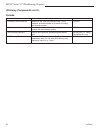
NEW K of new material (per inch) thickness
required =
X of listed
thickness K of listed material (per inch) material