


9
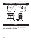
Stardance Direct Vent/Natural Vent Gas Heater
20012734
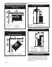
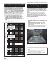
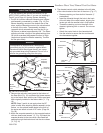
Vertical Termination - Direct Vent ONLY
A vertical vent system must terminate no less than 8’
(2.44m) and no more than 40’ (12m) above the appli-
ance flue collar. A restrictor plate (supplied) must be
used where specified in all vertically terminated vent
systems. (Fig. 8) NOTE: The restrictor plate supplied
with the vertical termination should be discarded.
Adjust the restrictor plate according to recom-
mendations in Figure 10. A vertically terminated vent
system must also conform to the following criteria:
• No more than three 90˚ elbows may be used.
• Two 45˚ elbows may be substituted for one 90˚ el
-
bow. No more than six elbows may be used.
• Vent must rise a minimum of 2 feet before offset is
used.
• Termination height must conform to roof clearance
as specified in Figure 9.
Vertical Run (in feet)
(Measure from the appliance flue collar to the top of the vent pipe.)
Horizontal Run (in feet)
ST132b
FDV28
Vertical
vent run
1/08
ST132b
Fig. 8 Vertical vent termination window.
*The restrictor Plate is used on Direct Vent Installations
Only.
All Vertical Termina-
tions in this area
Require use of the
Restrictor Plate*
Vertical Terminations
must be within this
area
Unacceptable Venting
Configuration
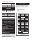
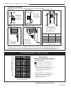
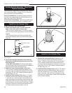
Restrictor Plate Adjustment
for Extended Pipe Runs
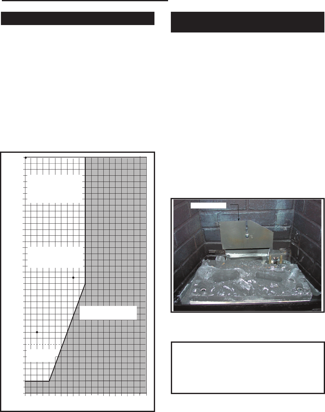
The Stardance stove is shipped with a restrictor plate
in the Parts Bag. Adjustments can be made by loosen-
ing the adjustment screw to allow the restrictor plate to
slide up or down. (Fig. 9) A guide for usage is shown in
Figure 10.
NOTE: Some installations may require some adjust-
ment by the installer for optimum flame appearance.
Optimum flame appearance is a flame that is not sub-
ject to tall, dirty yellow flames producing soot or flames
lifting off of the ember bed ports.
Restrictor Plate Adjustment
1. Remove the logs if installed.
2. Remove the adjustment screw in the back wall of the
firebox.
3. Install restrictor plate as shown in Figure 9 with
angle on plate on the top right side. Secure with
adjustment screw.
4. Adjust restrictor according to examples in Figure 10.
5. Install logs following log installation instructions.
Figure 10
Examples for Extended Run/Restrictor Plate Settings
1. Vertical 40’ (12 m) - restrictor plate lowered completely
down
2. Vertical 20’ (6 m), 90° elbow, 8’ (2.4 m ) horizontal -
restrictor plate lowered completely down
3. Vertical 10’ (3 m), 90° elbow, 2’ (305 mm) horizontal
- restrictor plate lowered completely down
Restrictor Plate
ST936
Fig. 9 SDDVT/SDDVTC restrictor plate.
No Restrictor
Plate