


19
Stardance Direct Vent - Rear Vent Gas Heaters
20012950
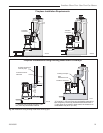
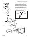
Vertical (Through the Roof)
Vent Assembly
NOTE: All vertically terminated installations must,
where specified, use the restrictor plate, to com-
ply with Vertical Termination Window (Fig. 8, Page
8), included in the hardware bag. The plate must be
installed as directed on Page 8, Figure 8.
Make certain the vent system conforms to all other
requirements for vertical termination as specified on
Page 9.
This installation will require you to first determine the
roof pitch and use the appropriate vent components.
Refer to Page 10, Figure 11.
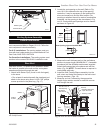
1. Locate the final position of the stove, observing all
clearances for both the vent and the stove.
2. Plumb to the center of the inner (4”) flue collar from
the ceiling above, and mark that location.
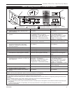
3. Cut the opening: (Page 17, Fig. 23)
9
³⁄₈” x 9³⁄₈” (240 x 240mm)
4. Plumb any additional opening through the roof or
other construction that may be needed. In all cases,
the opening must provide a minimum of 1” (25mm)
clearance to the vent pipe.
5. Place the stove in its final position.
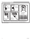
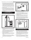
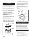
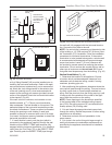
6. Install firestop(s) #7DVFS and Attic Insulation Shield
#7DVAIS as needed. (Fig. 31) If there is a room
above ceiling level, a firestop must be installed on
both the bottom and top sides of the ceiling joists.
If an attic is above ceiling level, an attic insulation
shield must be installed.
ST222
vent thru ceiling
12/99
#7DVAIS
Attic Insulation
Shield
#7DVFS
Firestop in
Upper Floor
#7DVFS
Firestop in
Ceiling
Use Four
8d Nails
ST222
Fig. 31 Install firestops and attic insulation shield.
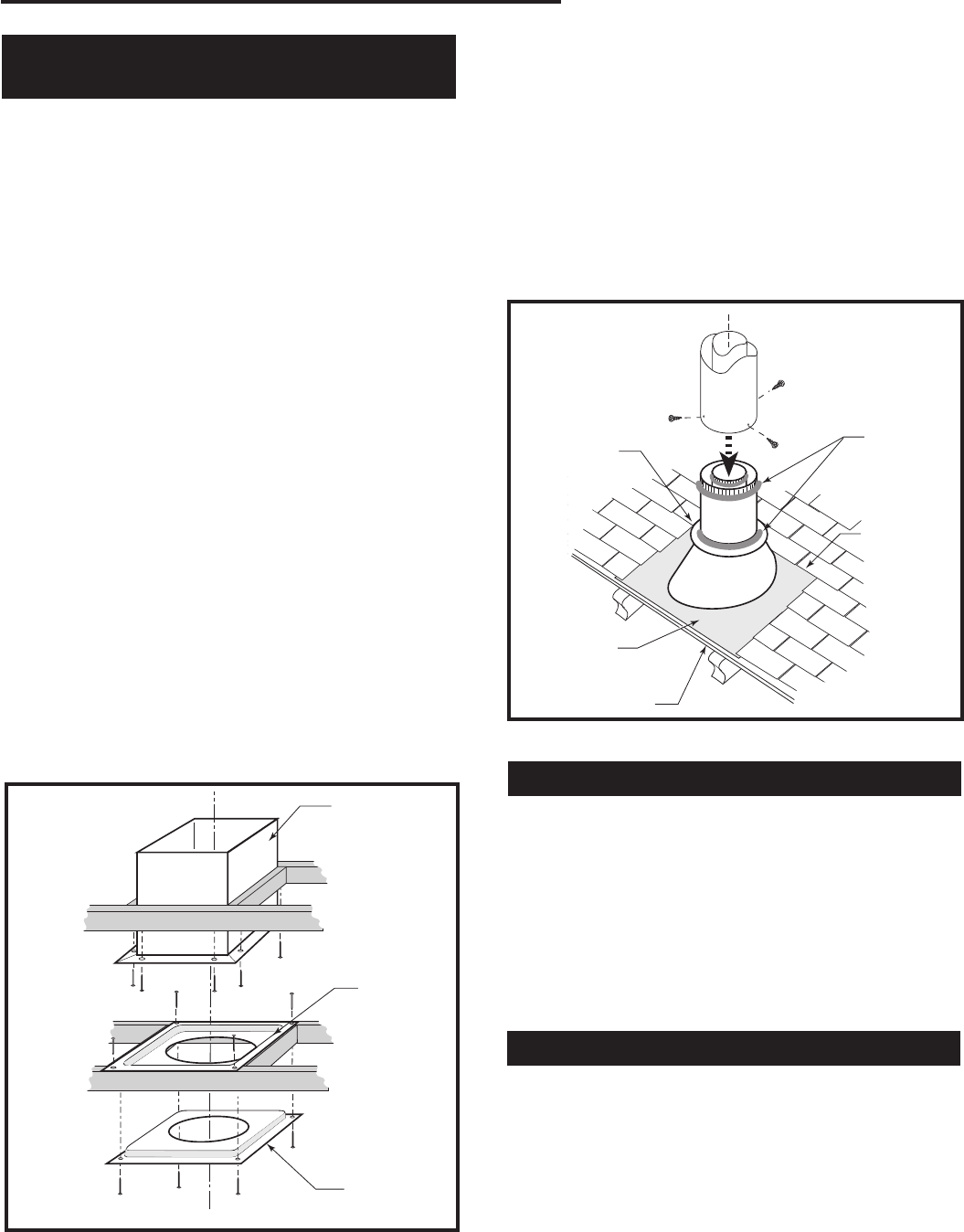
ST221
vent thru roof
12/99
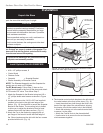
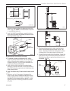
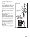
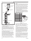
Storm
Collar
Sealant
Upper edge
of flange goes
under upper
shingles
Flashing
#7DVSKV (A,
B, or F) Roof
Support
Use three #5
sheet metal
screws at
each joint
ST221
Fig. 32 Roof support and flashing.
7. Install the appropriate roof support and flashing,
making certain that the upper flange of the flashing
base is below the shingles. (Fig. 32)
8. Install appropriate pipe sections until the vent run
reaches above the flashing. The enlarged ends of
the vent sections always face downward.
9. Install the storm collar and seal around the joints. (Fig.
32)
10. Add additional vent lengths to achieve the proper
overall height.
11. Install termination cap.
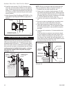
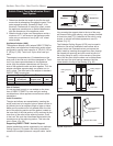
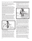
Vertical Through Existing Chimney
The heater must be vented to the outdoors through an
existing masonry or prefabricated fireplace chimney
system through the roof.
The heater is approved to be vented to the outdoors
through any solid-fuel fireplace chimney that has been
constructed or installed in accordance with the na-
tional, Provincial/State and local building codes and is
constructed of noncombustible materials. For Venting
Requirements, refer to Page 10. Refer to Venting Com-
ponents on Pages 12 & 13.
Fireplace Vent Termination Clearances
Observe the chimney-top vent termination clearances
specified in the instructions provided with those compo-
nents. Some considerations are:
• Obstructions or impediments to venting.
• Nearby combustible materials that could come into
contact with combustion exhaust gases.
• Other nearby openings within 9” (230 mm) through
which exhaust gas could reenter the building.