


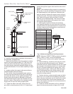

22
Stardance Direct Vent - Rear Vent Gas Heaters
20012950
Selkirk Direct-Temp Metalbestos Direct
Vent System
Installation Instructions
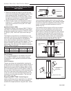
1. Determine whether the length of pipe fits the appli-
ance outlet by attempting to engage the parts. If the
parts engage smoothly, proceed to Step 2. If ob-
structions, interference or loose fit is noted, contact
the appliance manufacturer or Selkirk Metalbestos
with the dimensions of the appliance outlet.
2. Slide the length of pipe over the appliance outlet a
minimum of 1¹⁄₂” and screw to the appliance outlet
collar using a minimum of two (2) #8 x 1/4” sheet
metal screws.
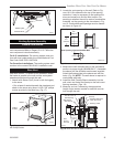
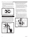
Appliance Adapter (AAV)
The appliance adapter (AAV) adapts DIRECT-TEMP to
most direct vent appliances incorporating outlet collars
configured to receive most common 4” (ID) 6⁵⁄₈” (OD) or
5” (ID) by 8” (OD) “Twist Lock” Style, direct vent sys-
tems.
The adapter incorporates two (2) indentations on the
outer wall of the inlet end, which are designed to “Twist
Lock” into place upon attachment to the appliance
outlet. Align the adapter indentations with the entry
slots of the appliance outlet and slide together. Turn the
adapter clockwise approximately one-quarter turn to
lock in place. The outlet end of the adapter is standard
DIRECT-TEMP construction.
Framing Dimension Table 1
Model DT Ceiling Support (CS) Cathedral Ceiling Wall Thimble
Diameter Firestop (FS) Support CCS) (WT)
4” 8¹⁄₄” x 8¹⁄₄” 10⁵⁄₈” x 10⁵⁄₈” 8¹⁄₄” x 8¹⁄₄”
5” 10
¹⁄₈” x 10¹⁄₈” 14¹⁄₂” x 14¹⁄₂” 10¹⁄₈” x 10¹⁄₈”
Use of Sealant
It is not required to apply or use sealant on the inner
liner of DIRECT-TEMP. For outer wall joint sealing
considerations, follow appliance manufacturer recom-
mendations.
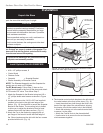
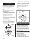
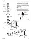
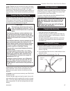
Joint Connection:
The pipe and elbows are assembled by inserting the
outlet (male) end of a length of pipe or elbow into the in-
let (female) end of an adjacent length of pipe or elbow.
Make sure the outlet end is fully seated within the inlet
end of the adjoining section and the gasket, located on
the inner liner of the inlet section is fully enclosed by the
inner liner of the outlet of the adjoining section. Push
in the Lock Tab such that it becomes seated within the
inward groove of the adjoining section. This locks the
joint in place. (Fig. 36)
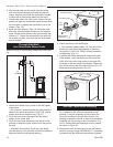
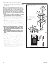
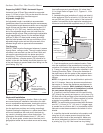
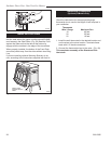
Supporting DIRECT-TEMP: Vertical Support
Vertical installations can be supported by two methods:
Ceiling Support (CS) (used in flat ceiling installation)
comes with a support plate and a support collar. Install
Gasket
Lock Tab
Inlet End
Outlet End
ST922
To Termination To Appliance
Fig. 36 Joint connection.
it by screwing the support plate to the top of the prop-
erly framed ceiling joist opening, using screws provided.
A round trim plate (TP) is attached to the ceiling, using
screws, to provide a finished appearance once in-
stalled. (Fig. 37)
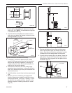
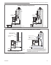
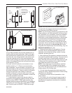
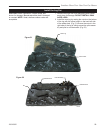
The Cathedral Ceiling Support (CCS) may be used in
pitched or flat ceiling installations and comes with a
support collar and a decorative two part square trim
plate. Install by inserting the support box down through
the framed joist opening (end with round hole first) in
the ceiling using tin snips, cut the corners of the open
end of the box such that the sides can be folded down
over the top of the joist framing members. Nail the
folded sides to the top of the framing. (Fig. 38)
Ceiling Support
Plate
Ceiling Support
Collar
Trim Plate
ST923
Fig. 37 Ceiling support.
Two Part Square
Trim Plate
Support Box
Support Box Collar
ST926
Fig. 38 Support box.