


14
Radiance Vent-Free Gas Heater
20004555
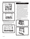
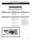
Install Log Set
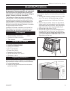
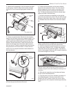
1. Remove the logs from their packaging, and inspect
each piece for damage. DO NOT INSTALL DAM-
AGED LOGS.
2. Install the rear left log by placing it on the sheet
metal shelf at the back of the firebox. (Fig. 23) The
log should touch the back wall of the firebox. Slide
the log to the left until the left side lines up with the
left bracket. (Fig. 23) When the log is in place the
left front corner of the log should rest on the decora-
tive grate.
3. Install the rear right log by placing it on the sheet
metal shelf at the back toward the right. Make
sure the right side of the log lines up with the right
bracket. (Fig. 23) NOTE: When the right and left rear
logs are in place, they should touch the back of the
firebox and each other.
4. Install the right log by engaging hole on the bottom
with pin on the right rear log. (Fig. 23) Set the bottom
of the log on the bracket and bring forward to come
in contact with decorative grate on right.
This appliance should only be connected
by a qualified gas technician. Test to
confirm manifold pressures as specified
below.
The Radiance Heater and its individual shutoff
valve must be disconnected from the gas supply
piping during any pressure testing of that system
at test pressures in excess of 1/2 psig (3.5 kPa).
The Radiance Heater must be isolated from the
gas supply piping system by closing its indi-
vidual manual shutoff valve during any pressure
testing of the gas supply piping system at test
pressure equal to or less than 1/2 psig.
There must be a gas shutoff between the stove
and the supply.
In order to connect Natural Gas, use a fitting
with 1/2” NPT on the valve side and 1/2” natural
gas supply line with an input of 35,000 BTUs at a
manifold pressure of 3.5” between minimum inlet
supply of 5.5” w.c. and maximum of 14.0” w.c.
In order to connect Propane, use a fitting with 1/2”
NPT on the valve side and 1/2” propane gas sup-
ply line with an input of 35,000 BTUs at a manifold
pressure of 11.0” between a minimum inlet supply
of 11.0” w.c. and maximum of 14.0” w.c.
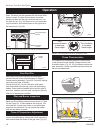
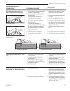
CAUTION
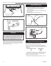
Connect the Gas Supply Line
Check the Rating Plate attached by a steel cable to the
firebox, to confirm that you have the appropriate firebox
for the type of fuel to be used.
This appliance should only be connected by a
qualified gas technician. Test to confirm manifold
pressures as specified below.
The Radiance Heater and its individual shutoff
valve must be disconnected from the gas supply
piping during any pressure testing of that system
at test pressures in excess of 1/2 psig (3.5 kPa).
The Radiance Heater must be isolated from the
gas supply piping system by closing its individual
manual shutoff valve during any pressure testing of
the gas supply piping system at test pressure equal
to or less than 1/2 psig.
There must be a gas shutoff between the stove and
the supply.
In order to connect Natural Gas, use a fitting with
3/8” NPT nipple on the valve side and 1/2” natural
gas supply line with an input of 35,000 BTUs at a
manifold pressure of 3.5” and minimum inlet sup-
ply for adjustment of 5.5” w.c.
In order to connect Propane, use a fitting with 3/8”
NPT nipple on the valve side and 1/2” propane gas
supply line with an input of 35,000 BTUs at a mani-
fold pressure of 11.0” and minimum inlet supply for
adjustment of 11.0” w.c.
Gas connection should be made in accordance with
current National Fuel Gas Code, ANSI Z223.1. Since
some municipalities have additional local codes, be
sure to consult you local authority.
Connect the gas supply and test for leaks. Use a 50/50
solution of liquid soap and water to test for leaks at gas
fittings and joints. NEVER test with an open flame.
Light the pilot according to the directions on page 16,
before going to the next step.
ST187
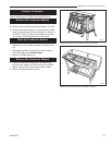
pull frame latches
11/99
ST672
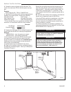
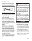
Fig. 22 Set glass frame in place and secure latches.
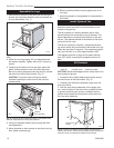
8. Install glass frame assembly by resting the bot-
tom edge of the frame on support brackets below the
front opening of the firebox. Swing the top edge of the
assembly toward the firebox, and center it. Fasten by
closing the latches over the top left and right edges of
the frame. (Fig. 22)