


- 11 -
CLEANING PROCEDURE
1. Turn off pilot light at gas valve.
2. Remove front glass.
3. Remove logs.
CAUTION: LOGS MAY BE HOT
4. Vacuum burner compartment especially around orifice/
primary air openings.
5. Reinstall logs.
6. Check pilot and main burner operation.
7. Reinstall front glass.
8. Recheck pilot and main burner operation.
9. Check visually the flame pattern and compare with Fig.
21 or 22.
Fig. 18a
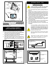
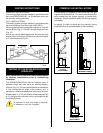
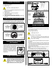
FLAME ADJUSTMENT (RN/RP MODELS)
For units equipped with Hi/Lo valves, flame adjustment
is accomplished by rotating the Hi/Lo adjustment knob
located near the centre of the gas control. (Fig. 18a & b)
L
O
H
I
Turn
counterclockwise
to increase
flame height.
Turn clockwise
to lower
flame height.
CERAMIC REFRACTORY
RFS42 ONLY
1. Remove bay window assembly and glass frame (see "Glass
frame Removal" section).
2. Remove logs from the unit.
LOGS MAY BE HOT
3. Remove refractory from packaging.
Refractory are fragile and must be handled with
care. Where at all possible, two hands should be
used when handling.
4. Take centre refractory piece and place it at the very back of
the firebox.
5. Take left or right side refractory and slide it along the side
of the firebox and on top of the bottom support channel. Be
sure to slide it back to hold the centre piece in place and the
leading edge faces forward.
6. Fasten top tab support against the refractory to hold it in
place.
7. Repeat steps 5 and 6 for remaining side refactory.
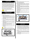
8. Insert refractory pieces into the Bay Window as per Fig. 23.
Leading
Edge
Leading
Edge
Left
Side
Centre
Right
Side
Fig. 22
Fig. 23
L
O
H
I
Turn
counterclockwise
to decrease
flame height.
Turn clockwise
to increase
flame height.
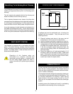
TEMPERATURE ADJUSTMENT
(TN/TP MODELS)
HI
OFF
PILOT
LO
Fig. 19
The Hi/Lo reference on the control knob (Fig. 19) is to
indicate a higher or lower temperature setting. This setting
controls the heat by reducing then
shutting off the flame as the desired
temperature is reached. Position
the control knob where it effectively
maintains a comfortable room
temperature.
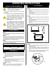
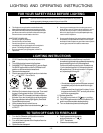
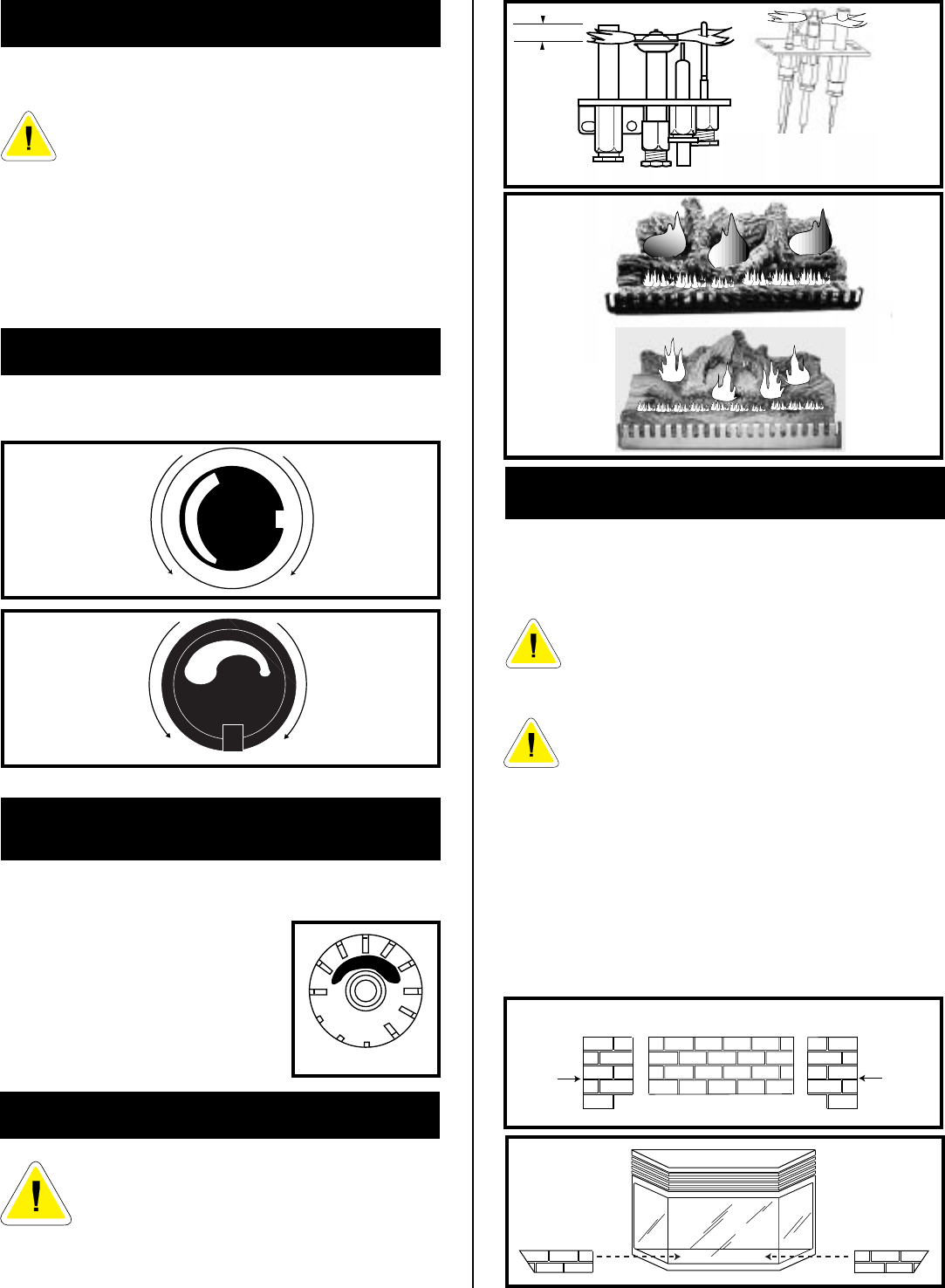
It is important to periodically perform a visual
check of the pilot and the burner flames.
Compare them to the pictorials illustrated
below
(Fig. 20, 21)
. If any of the flames
appear abnormal call a service person.
FLAME CHARACTERISTICS
Fig. 21
RFS22
RFS32
RFS42
3/8" - 1/2"
Fig. 20
Fig. 18b
SIT VALVE PSE VALVE