


- 5 -
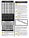
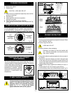
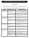
GAS INLET & MANIFOLD PRESSURES
Input Minimum
Input Maximum
Manifold Pressure
NATURAL
LP (Propane)
11" wc
13" wc
10" wc
4.5" wc
7" wc
3.5" wc
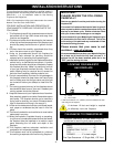
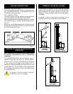
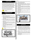
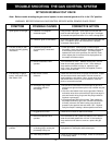
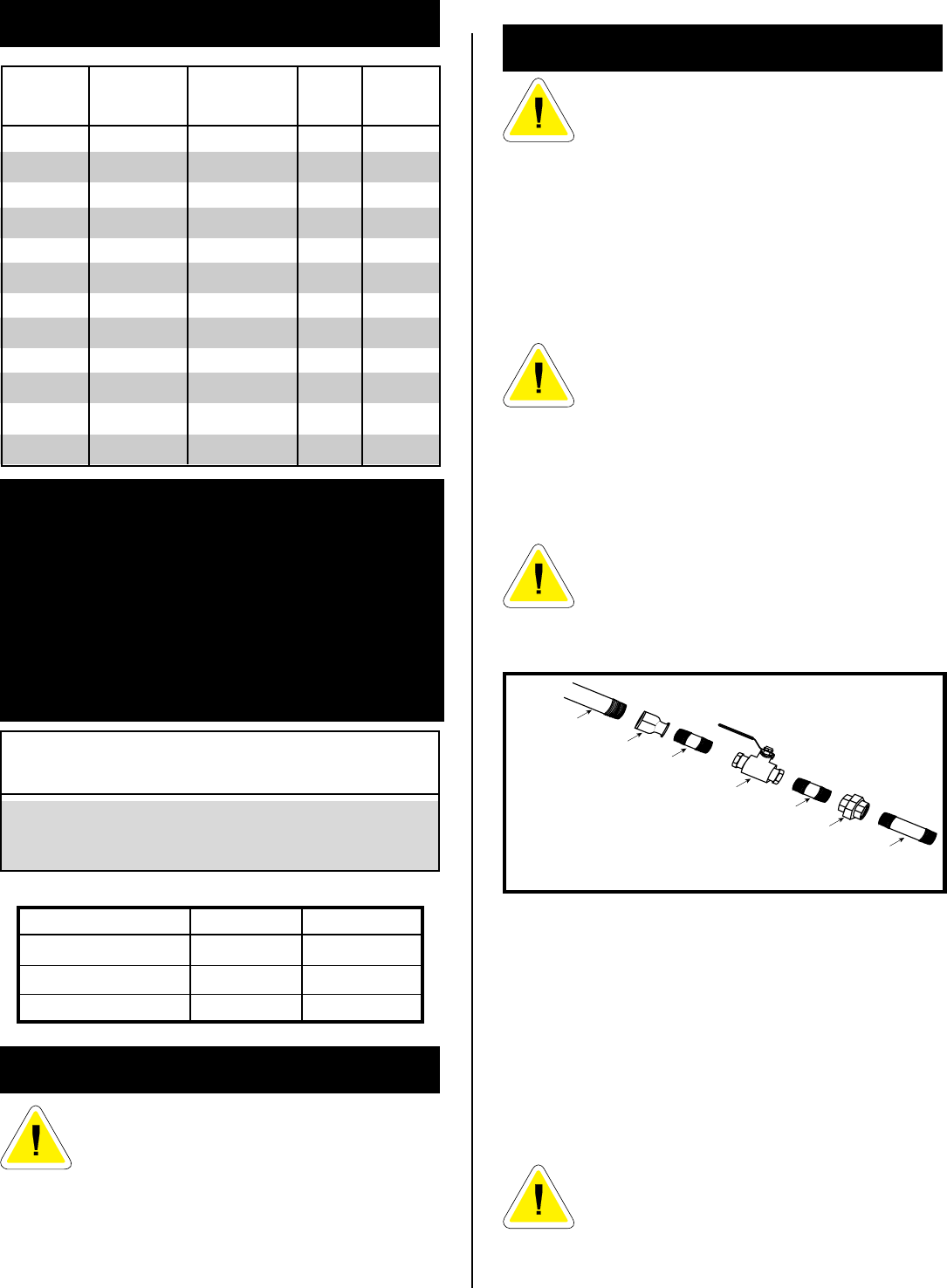
1/2" GAS SUPPLY
1/2" X 3/8" REDUCER
3/8" NIPPLE
3/8" NIPPLE
3/8" NIPPLE
3/8" X 3/8" SHUT OFF VALVE
3/8" UNION
DO NOT USE THIS FIREPLACE IF ANY PART
OF THIS FIREPLACE HAS BEEN UNDER
WATER. IMMEDIATELY CALL A QUALIFIED
SERVICE TECHNICIAN TO INSPECT THE
HEATER AND TO REPLACE ANY PART
CONTROL WHICH HAS BEEN UNDER
WATER.
When using copper or flex connector use only approved
fittings. Always provide a union when using black iron
pipe so that gas line can be easily disconnected for burner
or fan servicing. See Fig. 2. See gas specification for
pressure details and ratings.
The fireplace valve must not be subjected to any test
pressures exceeding 1/2 psi. Isolate or disconnect this or
any other gas appliance control from the gas line when
pressure testing.
Always check for gas leaks with a mild soap and
water solution. Do not use an open flame for
leak testing.
The gas control is equipped with a captured
screw type pressure test point, therefore it is not
necessary to provide a 1/8" test point up stream
of the control.
FOR U.S.A Installations consult the current National
Fuel Gas Code, ANSI Z223.1
GAS LINE INSTALLATION
When purging gas line, the front glass must
be removed.
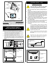
The gas pipeline can be brought in through the rear of the
fireplace as well as the bottom. Knockouts are provided on
the bottom behind the valve to allow for the gas pipe
installation and testing of any gas connection. It is most
convenient to bring the gas line in from the rear right
side of the valve, as this allows fan installation or
removal without disconnecting the gas line.
The gas line connection can be made with
properly tinned 3/8" copper tubing, 3/8" rigid
pipe or an approved flex connector. Since
some municipalities have some additional
local codes, it is always best to consult your
local authority and the CAN/CGA- B149 (.1 or
.2) installation code.
PREPARATION
The use of wall paper adjacent to this fire-
place is not recommended, as the high heat
given off by this fireplace may adversely
effect the binders in the adhesive used to
apply the wallpaper.
Before beginning, remove the glass door from the fireplace
(See page 9). Also check to make sure there is no hidden
damage to the fireplace. Take a minute and plan out the
gas, vent and electrical supply.
Fig. 2 Typical gas supply installation
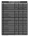
GAS SPECIFICATIONS
MAX. MIN.
INPUT INPUT
MODEL FUEL GAS CONTROL B.T.U.H B.T.U.H.
RFS22RN Natural Gas Millivolt Hi/Lo 30,000 21,000
RFS22RP Propane Gas Millivolt Hi/Lo 30,000 22,500
RFS22TN Natural Gas Thermostatic 30,000 21,000
RFS22TP Propane Gas Thermostatic 30,000 22,500
RFS32RN Natural Gas Millivolt Hi/Lo 30,000 21,000
RFS32RP Propane Gas Millivolt Hi/Lo 30,000 22,500
RFS32TN Natural Gas Thermostatic 30,000 21,000
RFS32TP Propane Gas Thermostatic 30,000 22,500
RFS42RN Natural Gas Millivolt Hi/Lo 40,000 28,000
RFS42RP Propane Gas Millivolt Hi/Lo 37,000 27,750
RFS42TN Natural Gas Thermostatic 40,000 28,000
RFS42TP Propane Gas Thermostatic 37,000 27,750
The installation of your Majestic Fireplace
must conform with local codes, or in the
absence of local codes, with National Fuel
Gas Code, ANSI Z223.1 latest edition, or CAN
1 B1-149.1 and .2 Installation Code.
(EXCEPTION: Do not derate this appliance
for elevations up to 4,500 ft. (1,370mm).
Maintain the manifold pressure at 3.5 inches
W.C. for Natural Gas and 10 inches W.C. for
LP gas.)
ANSI.Z21.88a-1998 / CSA 2.33a - M98
Vented Gas Fireplace Heaters
RFS22 / RFS32 / RFS42
CERTIFIED TO