


31
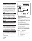
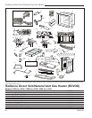
Radiance Direct Vent /Natural Vent Gas Heater
20004188
CO100
Gas conversion
HI-LO knob
3/15/99 djt
L
O
H
I
L
O
H
I
Cap
Hi-Lo
Knob
Lift Open
Center Screw
CO100
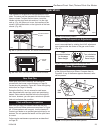
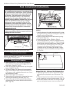
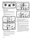
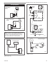
Fig. 55 Remove center screw from Hi-Lo knob.
14. Tighten screw (do not over tighten), replace cap.
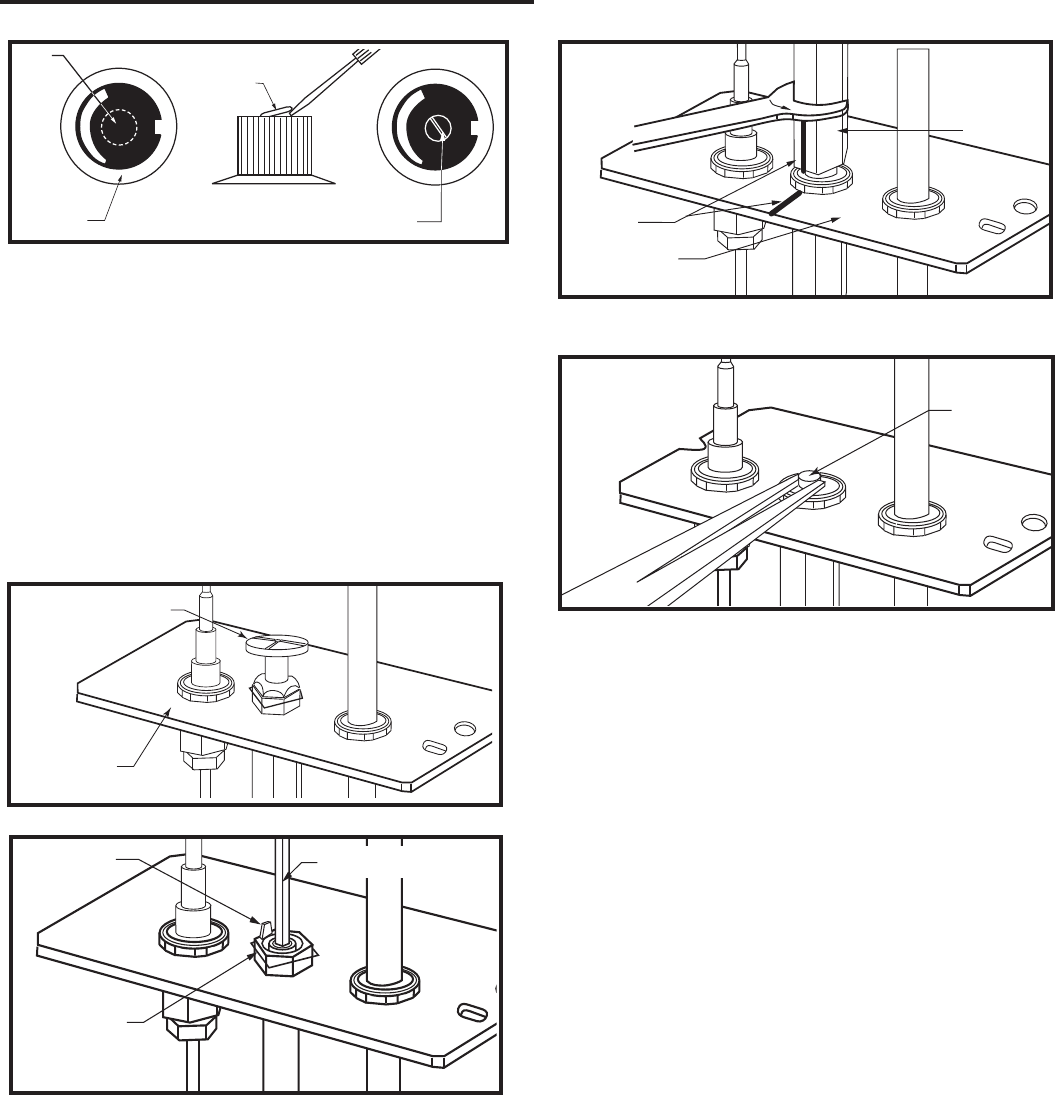
15. Locate pilot. (Fig. 53)
16. Replace pilot orifice.
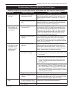
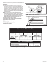
Pilot Type 1 (SIT Pilot)
• Remove pilot hood by lifting up. (Fig. 56) Do not
remove the snap ring to remove the pilot hood.
NOTE: It is not necessary to remove the pilot tube
for conversion.
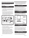
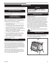
• Remove pilot orifice with allen wrench. (Fig. 57)
• Install the conversion orifice.
• Reinstall pilot hood. Be sure to align hood with
index tab.
CO105a
gas conversion
Pilot
1/28/00 djt
Pilot Hood
Pilot
Bracket
CO105a
Fig. 56 Remove pilot hood.
CO106a
DV360/580
Gas Conversion
Pilot2
1/28/00 djt
Index Tab
Snap Ring
Allen Wrench
CO106a
Fig. 57 Remove pilot orifice.
CO105
Gas Conversion
Pilot
2/15/99 djt
Pilot Hood
Index
Marks
Pilot Bracket
CO105
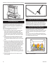
Fig. 58 Remove pilot hood. (Your pilot may have a different
appearance.)
CO106a
Gas Conversion
Pilot (Vermont)
7/19/99 djt
Pilot
Orifice
CO106b
Fig. 59 Remove pilot orifice.
Pilot type 2 (Honeywell Pilot)
• Loosen pilot hood turning counterclockwise using a
7/16” wrench. (Fig. 58) NOTE: You may use pen-
etrating oil to prevent pilot hood threads from seizing
up.
• Remove pilot orifice with needlenose pliers. (Fig.
59) NOTE: Use a wrench to hold pilot tube in place
while removing the orifice.
• Install the conversion orifice.
• Reinstall pilot hood and tighten until mark on pilot
hood aligns with mark on pilot bracket.
NOTE: Be sure burner leg remains at a 90° angle to
firebox base after conversion.
Models 3352, 3354, 3390 thru 3399 (RF Models) Only
17. Follow procedure for pilot type 2 to replace pilot
orifice.
18. Remove and replace plug on lower right hand side
of the valve; Red for LP and Blue for NG. (Page 26,
Fig. 49)
19. Remove motor top cap. Depress and turn center
plunger until arrow points to correct screw. Red for
LP and Blue for NG. NOTE: Plunger will “snap” into
NG position when arrow is close to blue screw. It will
not “snap” at LP (Red) position. (Fig. 60)
20. Insure manifold pressure remains between 3.2”
- 3.5” w.c. for NG and 9.5” - 10” w.c. for LP. To adjust
the manifold pressure, for NG, using a torque #10 key
turn the blue screw clockwise to increase the manifold
pressure. Turn the screw counterclockwise to de-
crease the pressure. Use the red screw to adjust LP.
21. Replace motor top cap.