


13
NV360/580 Series
20003565
is not, turn the unit off and check for causes creating
the lack of adequate draft.
Do not operate the unit until lack of ad-
equate draft has been determined and
rectified.
First Firing
Upon completing the gas line connection, a small
amount of air will be trapped in the line. When first
lighting the unit with pilot light, it will take a few minutes
to purge the trapped air. Once purging is complete, the
pilot and burner will light and operate as indicated in the
instruction manual. Subsequent lightings of the appli-
ance will not require purging.
When lit for the first time, the appliance will emit a slight
odor for an hour or two. This is due to paint and lubri-
cants used in the manufacturing process. After each
lighting, vapor may condense and fog the glass; this
moisture disappears in a few minutes of burning.
FP1197
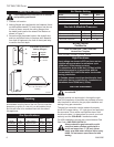
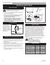
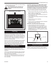
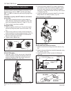
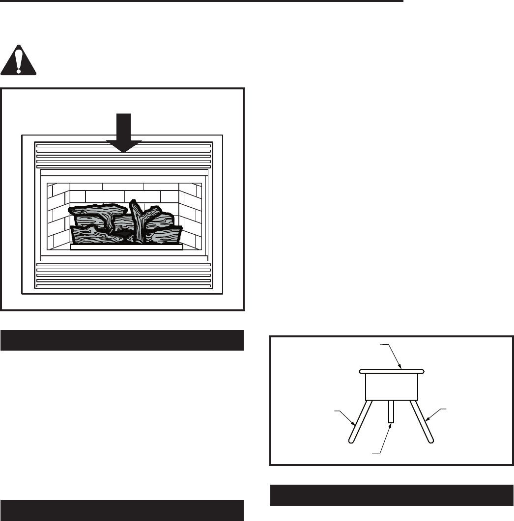
draft test location
2/27/02 djt
Test for Draft at This Location
FP1197
Fig. 17 Draft test location.
Vent Safety Switch
This fireplace incorporates the use of a Vent Safety
Shut-off Switch. The sensor and wiring are factory
installed and should not be removed or altered during
installation.
In the event of total flue blockage the system will detect
the increased heat buildup and will automatically shut
down the main burner assembly.
The sensor is located above the firebox behind the top
louvre assembly. It is accessible by removing the top
louvre assembly.
CAUTION: The firebox, Vent Safety Switch sensor
and surrounding panels become very hot during
normal operation. Allow time for the components to
cool before carrying out any service or inspection.
If the sensor is activated and shuts off the burner as
-
sembly, the following procedure should be followed:
• Observe that the pilot flame is still "ON". If the pilot
flame has gone out the reason for the fireplace shut
down is not the vent safety switch.
• Turn the pilot flame "OFF" and close all controls. Al-
low the fireplace to cool.
• Check the flue and venting component for blockage
or restrictions.
• Remove the front louvre assembly.
• Locate the sensor.
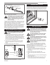
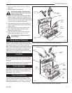
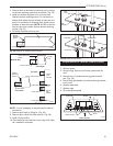
• Reset the sensor by pressing the reset pin between
the two wire terminals. (Fig. 18)
CAUTION: The components may still be hot.
• Light the fireplace and check for downdrafts.
• Operate the fireplace in the normal manner. If the
burner assembly shuts down again after a period
of operation, DO NOT ATTEMPT TO RESET THE
SENSOR AGAIN. Turn off the fireplace and contact
your service technician.
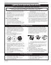
FP1160
Vent safety switch
11/2/01 djt
Sensor
Wire Terminal
Reset Pin
Wire Terminal
FP1160
Fig. 18 Vent safety switch.
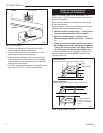
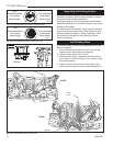
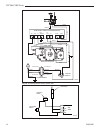
Electrical Connection
The sensor is wired in series between the wall mounted
"ON/OFF" switch and the Electronic Ignition Module
(Fig. 19) or the thermopile and the gas valve (Fig. 20).