


17
10002428
Vermont Castings, Majestic Products DVRT36/39/43
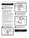
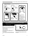
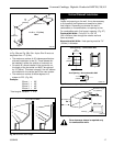
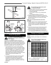
In Fig. 25a and Fig. 25b, Dim. A plus Dim. B must not
be greater than 17’ (5.2m).
• The maximum number of 45° elbows permitted per
side wall installation is two (2). These elbows can
be installed in either the vertical or horizontal run.
• For each 45° elbow installed in the horizontal run,
the length of the horizontal run MUST be reduced
by 18” (45cm). This does not apply if the 45° elbows
are installed on the vertical part of the vent system.
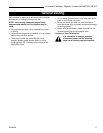
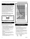
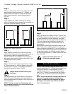
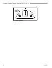
• The maximum number of elbow degrees in a
system is 270°. (Fig. 26)
Example:
Elbow 1 = 90°
Elbow 2 = 45°
Elbow 3 = 45°
Elbow 4 = 90°
Total angular variation = 270°
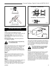
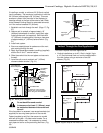
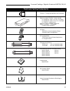
Vertical Sidewall Installation
Step 1
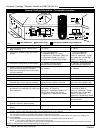
Locate vent opening on the wall. It may be necessary
to first position the fireplace and measure to obtain
hole location. Depending on whether the wall is
combustible or noncombustible, cut opening to size.
For combustible walls, first frame in opening. (Fig. 27)
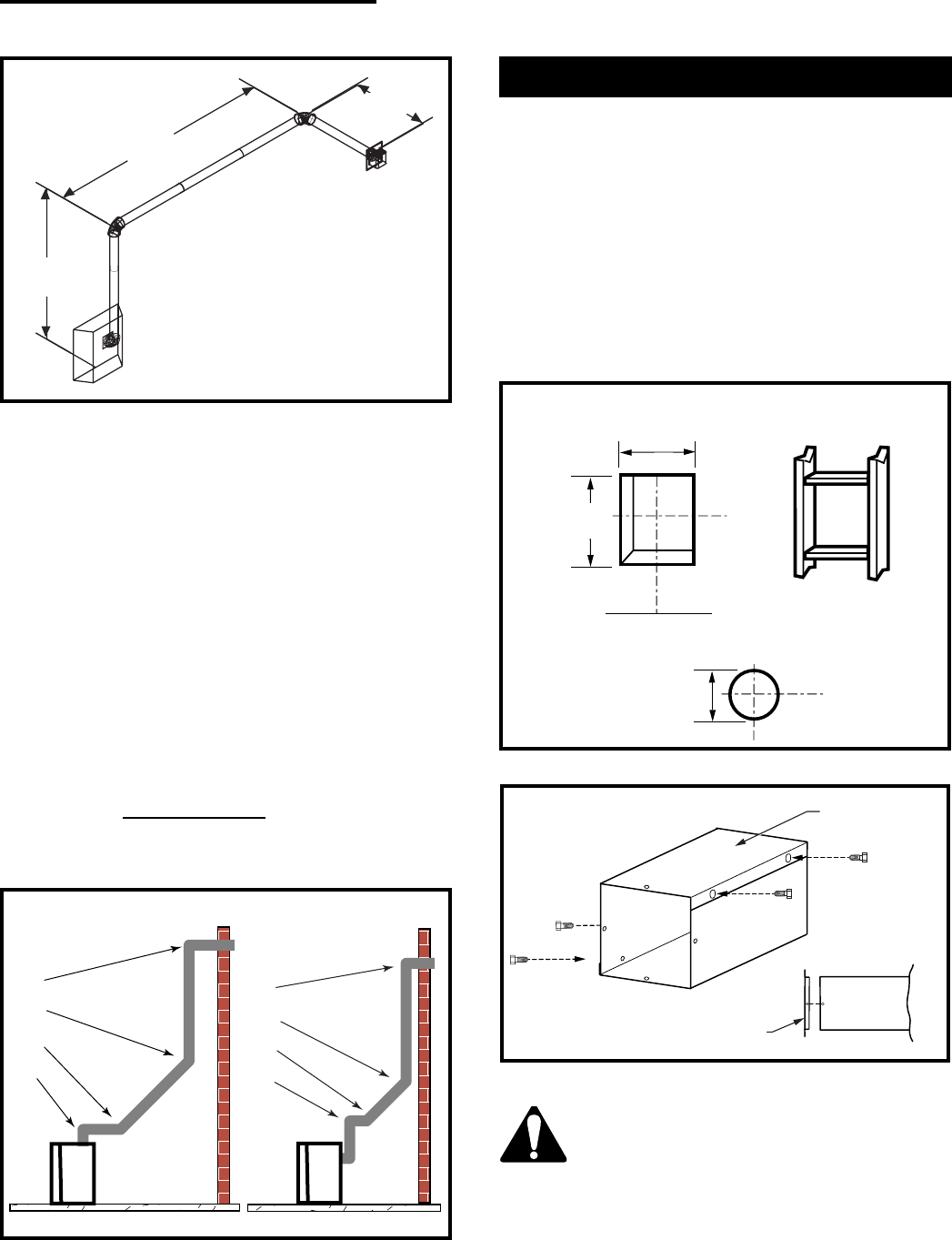
Combustible Walls: Cut a 9³⁄₈” H x 9³⁄₈” W
(240 x 240mm) hole through the exterior wall and
frame as shown.
Noncombustible Walls: Hole opening must be 7¹⁄₂”
(190mm) in diameter.
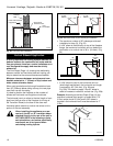
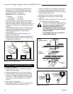
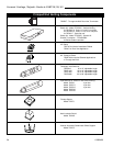
Zero clearance sleeve is required only
for combustible walls.
1
2
3
4
1
2
3
4
1 + 2 + 3 + 4 = 270°
FP1180
Fig. 26 Maximum elbow usage.
Vent Opening - Combustible Wall
Framing Detail
Fireplace Hearth
7¹⁄₂” Dia.
(190mm)
VO584-100
Vent Opening - Noncombustible Wall
9³⁄₈”
(240mm)
Fig. 27 Locate vent opening on wall.
9³⁄₈”
(240mm)
90° Elbow = 3’
V584-201
A + B = 17’ (5.2m)
Max.
Fig. 25b Maximum vent run with elbows.
10’
(3048mm)
A
7’
(2134mm)
B
7’ 6”
(2286mm)
Fig. 28 Adjustable zero clearance sleeve.
CFM135a
Maximum Length
12” (305mm)
#8 Screws (2)
Side View
Firestop
#8 Screws (2)