


- 27 -
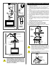
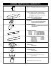
6. Hang Bay Window Frame assembly over existing glass
frame.
Do not remove existing glass frame
7. Re-install top louvre assembly.
Remove all plastic from brass trims
8.
Open the Bottom Bay Louvre door and screw two (2) self
tapping screws (as per step 1 above) to the bottom of the
unit where the hinges were.
9. Bottom brass trim is removable when unit is installed with
marble or tile surround which cover the fireplace bottom.
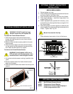
Fig. 56
CERAMIC REFRACTORY
CERAMIC REFRACTORY
BOTTOM BAY LOUVRE
SCREWS
BAY WINDOW FRAME
BOTTOM
BRASS
TOP LOUVRE
SPACERS
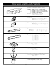
OPTIONAL BAY WINDOW INSTALLATION
for DBR36/DBR39
1. Remove existing bottom louvre and hinges from fire-
place. (Set aside the two (2) self tapping screws).
2. Remove existing top louvre from fireplace.
3. Remove two (2) pieces of ceramic refractory from Bay
Frame Window; considering that these are very fragile
pieces handle them with special care!
4. Assembly Bay Window Frame to Bottom Bay Louvre by
using four (4) machine screws (from top to bottom), four
(4) nuts (in the bottom) and four (4) spaces (all supplied
with the kit) through the existing four (4) holes in the
bottom of the ay Window Frame and in the top of the
Bottom Bay Louvre. Spacers to be placed between the
Bay Window Frame and the Bottom Bay Louvre.
5. Insert two (2) pieces of ceramic refractory into the Bay
Window Frame as per drawing below.
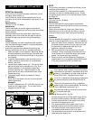
Fig. 55
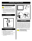
ELECTRICAL BOX
GAS INLET HOLE
INSIDE VIEW
FASTENING
SCREWS
OUTSIDE VIEW
OPTIONAL EB1 (Receptacle) Hook-Up
The EB-1 Electrical junction box when fitted and
correctly wired gives an easy and convenient power
outlet for the optioal fan kit.
If the EB-1 electrical junction box is being fitted
the fireplace must be electrically connected and
grounded in accordance with local codes or, in
the absence of local codes, with the current CSA
C22.1 Canadian Electric Code.
For U.S.A. installations follow the local codes and
the national electrical code ANSI/NFPA No 70.
It is strongly recommended that the wiring of the
EB-1 Electrical Junction Box be carried out be a
licensed electrician.
Ensure that the power to the supply line has
been disconnected before commencing this
procedure.
To install and connect the EB-1 box to the house
electrical supply follow the steps below.
1. Disconnect the power to the electrical supply line.
2. Remove the cover plate over the EB-1 knock-out
the side of the appliance, retain the screw that held
the plate.
3. Remove the front cover of the EB-1 box.
4. Remove the plug socket assembly from the EB-1
box.
5. Feed the electrical supply line in through the EB-1
opening in the side of the appliance and then
through the back of the EB-1 assembly, Fig 55.
6. Connect the ground wire of the supply line to the
green screw of the socket assembly.
7. Connect the white wire of the power line to the
chrome screw of the socket assembly.
8. Connect the black wire of the power supply line to
the brass screw (polarized) of the socket assembly.
9. Refit the socket assembly back into the electrical
box and replace the front cover plate. Secure the
cable with the clamp on the outside of the EB-1 base
plate and refit the EB-1 assembly to the appliance
with the screw removed in step 2.
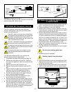
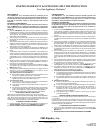
Fig. 54
Black
White
Ground
FAN
TEMPERATURE
SENSOR
SPEED
CONTROL
Method B (Using the EB-1 Box.)
For instruction on wiring the EB-1 Electrical Junction Box
see the chapter EB-1 Electrical Box.