


1818
Vermont Castings Jefferson Direct Vent/Natural Vent Gas Heater
20002191
This installation will require you to first determine the
roof pitch and use the appropriate vent components.
Refer to Figures 8 and 9 on pages 8 and 9.
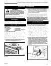
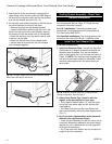
1. Locate the final position of the stove, observing all
clearances for both the vent and the stove.
2. Plumb to the center of the inner (4”) flue collar from
the ceiling above, and mark that location.
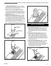
3. Cut the opening:
CFM System: 9³⁄₈” x 9³⁄₈” (240mm x 240mm)
DuraVent System: 10” x 10” (254mm x
254mm)
4. Plumb any additional opening through the roof or
other construction that may be needed. In all cases,
the opening must provide a minimum of 1” (25mm)
clearance to the vent pipe.
5. Place the stove in its final position.
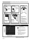
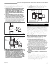
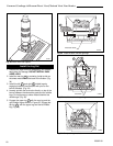
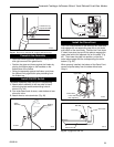
6. Install firestop(s) #7DVFS and Attic Insulation Shield
#7DVAIS as needed. (Fig. 30) If there is a room
above ceiling level, a firestop must be installed on
both the bottom and top sides of the ceiling joists. If
an attic is above ceiling level, an attic insulation
shield must be installed.
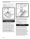
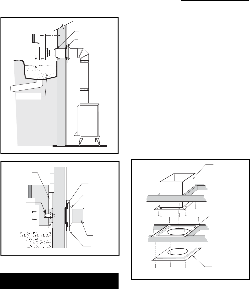
Recessed Wall
Sheet Metal
Screws and
Bracket
Wall Screws
and Anchors
Waterproof Seal
Around Pipe
ST219
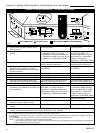
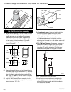
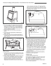
Fig. 29 Use extension brackets to mount snorkel against
recessed wall.
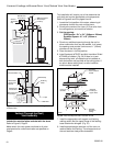
Firestop
Finishing
Collar
7” Pipe
Wall Plate
Waterproof Seal
Around Pipe
Firestop
Window Well
Drain
4” Clearance
Snorkel
Termination
Cap
Wall Screws
and Anchors
ST218
Gravel
Fig. 28 Snorkel kit installation.
Vertical (Through the Roof)
Vent Assembly
Note that all vertically terminated installations must
include the restrictor plate included with the stove.
Refer to Figure 8, Page 8.
Make certain the vent system conforms to all other
requirements for vertical termination as specified on
Page 8.
#7DVAIS
Attic Insulation
Shield
#7DVFS
Firestop in
Upper Floor
#7DVFS
Firestop in
Ceiling
Use Four
8d Nails
ST222
Fig. 30 Install firestops and attic insulation shield.
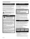
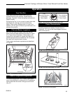
7. Install the appropriate roof support and flashing,
making certain that the upper flange of the flashing
base is below the shingles. (Fig. 31)
8. Install appropriate pipe sections until the vent run
reaches above the flashing. The enlarged ends of
the vent sections always face downward.