


8
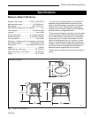
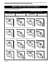
Madison Woodburning Stove
30001453
Floor Protection
A tremendous amount of heat radiates from the
bottom plate of your Madison. The floor area directly
under and around the stove will require protection from
radiant heat as well as from stray sparks or embers
that may escape the firebox.
Heat protection is provided through the use of a
Bottom Heat Shield #1892. Spark and ember protec-
tion must be provided by a floor protector constructed
with noncombustible material as specified.
Most installations will require that the bottom heat
shield be attached. Only when the stove is placed on a
completely noncombustible surface such as unpainted
concrete over earth may it be used without the heat shield.
Even when the bottom heat shield is installed, you
must provide special protection to the floor beneath.
For installations with the heat shield attached, use a
noncombustible floor protector such as 1/4” non-
asbestos mineral board or equivalent, or 24 gauge
sheet metal. The floor protector may be covered with a
noncombustible decorative material if desired. Do not
obstruct the space under the heater.
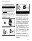
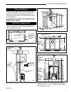
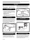
Protection requirements vary somewhat between the
United States and Canada as follows:
For U.S. installations the floor protector is required
under the stove and must extend at least 18” from the
front of the stove (“D”, Fig. 12), at least 4” from the
right side and rear (“C”, Fig. 12) and 16” from the left
side (“E”, Fig. 12). It must also extend under the
chimney connector and 2” to either side (“F”, Fig. 12).
To meet these requirements, a floor protector must be
at least 48” wide (“A”,Fig. 12) and 48” deep (“B”,Fig.
12)
In Canada, a noncombustible floor protector is re-
quired under the heater also. The floor protector must
extend 18” (457mm) to the front (D), and 8” (203mm)
from the right side (C) and rear (C) and 18” (457mm)
from left side (E).
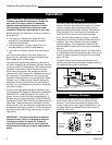
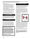
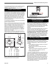
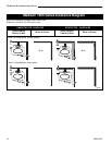
Fig. 9 Wall Pass-through using single wall chimney
connector with a ventilated steel thimble.
Min. 6"
(152mm)
Chimney clearance to sheet
steel supports and combustibles
2" (51mm) Min.
Glass Fiber
Insulation
Chimney Connector
Chimney Flue
Steel Thimble
with two 1"
(25mm) Ventilated
Channels
Masonry Chimney
constructed to NFPA 211
24 ga.Sheet
Steel Supports
ST274
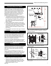
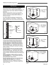
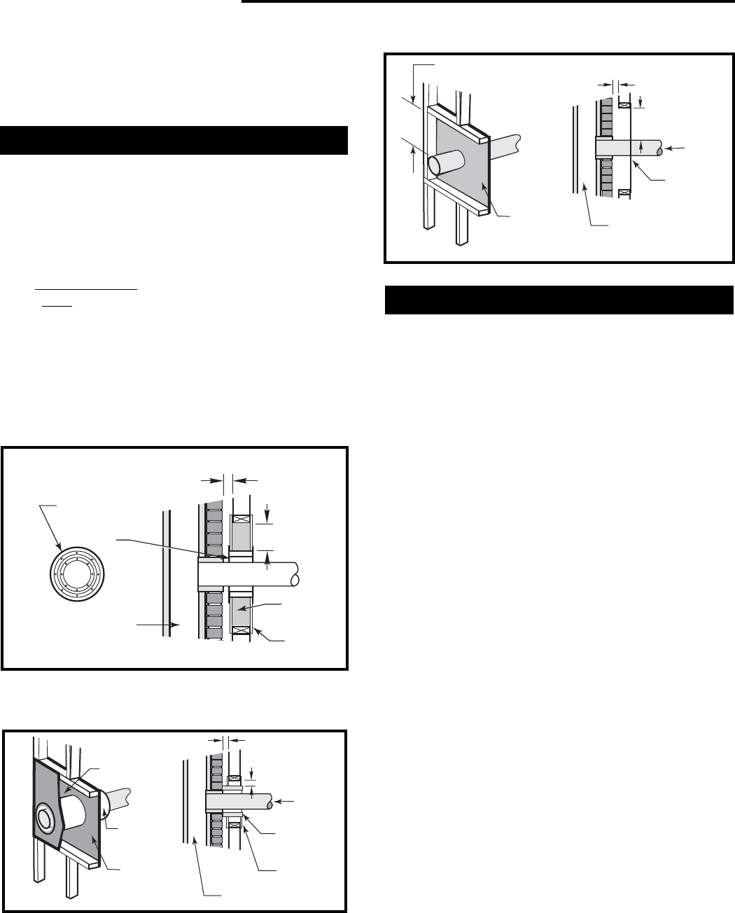
• Placing a chimney connector pipe inside a section
of 9" (230 mm) diameter, solid-insulated, factory-
built chimney, with two inches of air space between
the chimney section and combustibles. (Fig. 10)
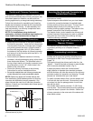
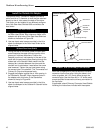
Canadian Requirements:
In Canada, the Canadian Standards Association has
established specific guidelines regarding wall pass-
though design. Figure 11 shows one approved method
in which all combustible material in the wall is cut away
to provide the required 18" (457mm) clearance around
the connector. The resulting space must remain
empty. A flush-mounted sheet metal cover may be
used
on one side only. If covers must be used on both
sides, each cover must be mounted on noncombus-
tible spacers at least 1" (25mm) clear of the wall. Your
local dealer or your local building inspector can provide
details of other approved methods of passing a chim-
ney connector through a combustible wall.
In Canada, this type of installation must conform to
CAN/CSA-B365, Installation Code for Solid Fuel
Burning Appliances and Equipment.
Fig. 11 CSA approved Wall Pass-through.
24 ga.Sheet
Steel Support
24 ga. Sheet
Steel Support
(one side only)
Min. 18"
(460mm)
Chimney clearance to sheet steel
supports and combustibles
2" (51mm)
Min.
Chimney Flue
Chimney
Connector
Masonry Chimney
constructed to CAN/CSA-
B365
Min. 18"
(460mm)
ST276
Fig. 10 Wall Pass-through with ventilated steel thimble.
24 ga. Sheet
Steel Supports
24 ga. Sheet
Steel Supports
2" (51mm) Min.
Chimney clearance to sheet steel
supports and combustibles
2" (51mm)
Min.
Chimney Flue
2" (51mm) Min.
air space
Prefab
Chimney
Section
Prefab
Chimney
Section
Chimney
Connector
Masonry Chimney
constructed to NFPA 211
ST275