


10
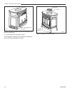
UVS27 Vent-Free Gas Heater
20007068
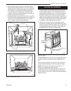
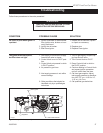
Glass & Catalyst Installation
CAUTION: Air shutter on Natural Gas units
must be adjusted when installing glass and
catalyst for proper operation. LP units do
not use an air shutter.
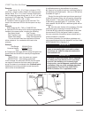
1. Remove screen. (Fig. 12) Remove rear, left and right
log bracket assembly by unfastening the two screws
which hold the burner in place.
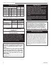
Thermostat Wire / Gauge Maximum Run
18 40 feet
20 25 feet
22 16 feet
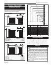
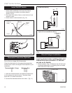
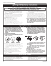
Thermostat Connection (Optional)
Use only a thermostat rated for 500 - 750 millivolts.
Do not use low voltage (24V) thermostats.
Check the table below for the appropriate gauge ther-
mostat wire to use for the length of lead required in your
installation.
1. Install the wall thermostat in the desired location and
run the wires to the stove location. Terminate these
leads with 1/4” female connectors.
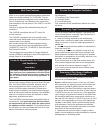
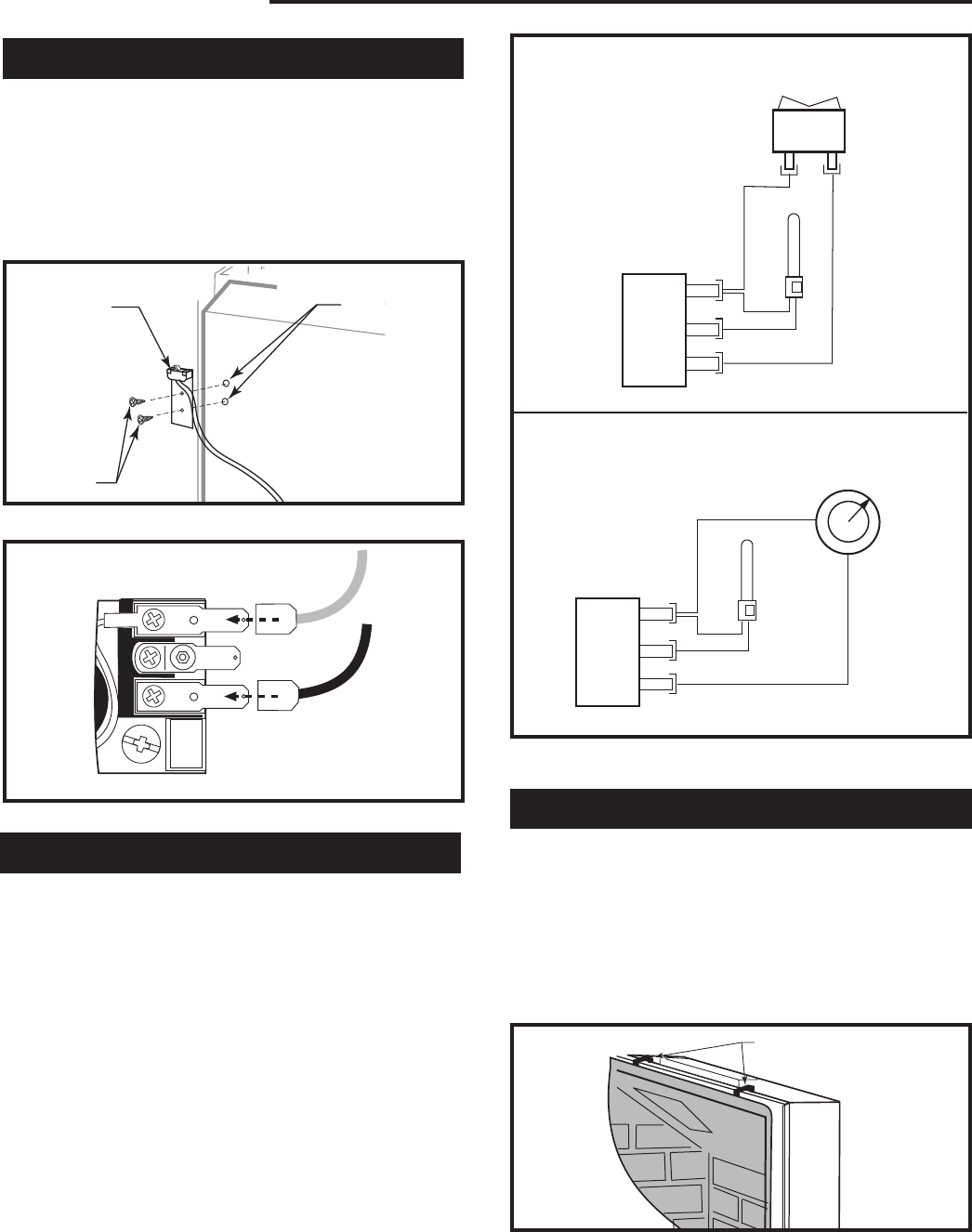
2. Connect the thermostat wires to the valve. (Fig. 11)
OFF
ON
Thermostat
(Optional)
Therm
opile
Black
Black
Millivolt
Gas Valve
St124b
on/off/switch
wiring
1/11/00 djt
TP/TH
TP
TH
On/Off Switch Wiring
Optional Thermostat/Remote Wiring
ST124b
ST124c
Fig. 11 ON/OFF switch and optional Thermostat/Remote
wiring.
Thermostat/Remote
(Optional)
Therm
opile
Black
Black
Millivolt
Gas Valve
St124c
Thermostat
wiring
1/11/00 djt
TP/TH
TP
TH
ST713
UVS27
screen removal
1/02
ST713
Fig. 12 Remove screen.
Screen Hooks
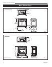
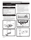
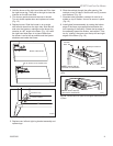
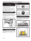
Install ON/OFF Switch
The switch assembly parts are found in the parts bag.
1. Attach switch assembly to left rear side of stove
shroud using two screws and existing holes in
shroud. (Fig. 9)
2. Run wires down back of stove, under bottom of rear
shroud to valve.
3. Attach wires to valve terminals. (Fig. 10)
TP
TH
TPTH
ST228
attach switch
wires to valve
12/99
ST228
Fig. 10 Attach switch wires to valve.
ST315
attach switch assy
1/31/00 djt
Existing
Holes
Switch As-
sembly
Screws
ST315
Fig. 9 Attach switch assembly to rear shroud.