


12
Radiance Vent-Free Gas Heater
20004555
MOTOR
SNAPSTAT
ON/OFF
RHEOSTAT
WHT
WHT
BLK
BLK
BLK
GR
N
BLK
POWER
ST196
FK26 fan diangram
11/99
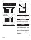
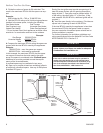
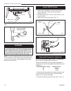
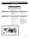
Fig. 15 #2767 / FK26 Fan Wiring Diagram
Disconnect power
before servicing.
ST196
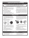
The optional fan kit is equipped with a three-prong
(grounding) plug for your protection against shock
hazard and should be plugged directly into a prop-
erly grounded three-prong outlet. Do not cut or
remove the grounding prong from this plug.
WARNING
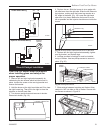
NOTE: If you are installing the fan kit after the stove is
in its final location, follow same steps mentioned previ-
ously with the exception of disengaging only the right
side of the outer shroud.
ST347a
JUV
FK28
rheostat install
9/21/00
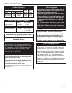
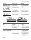
Rheostat
Retaining Nut
Control Knob
ST347a
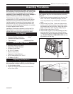
Fig. 14 Attach rheostat to control panel. Valve may look dif-
ferent.
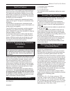
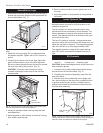
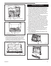
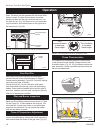
Install ON/OFF Switch
The switch assembly parts are found in the parts bag.
1. Attach switch assembly to left rear side of stove
shroud using two screws and existing holes in
shroud. (Fig. 16)
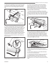
2. Run wires down back of stove, under bottom of rear
shroud to valve.
3. Attach wires to valve terminals. (Fig. 17)
TP
TH
TPTH
ST228
attach switch
wires to valve
12/99
ST228
Fig. 17 Attach switch wires to valve.
ST315
attach switch assy
1/31/00 djt
Existing
Holes
Switch As-
sembly
Screws
ST315
Fig. 16 Attach switch assembly to rear shroud.
Thermostat Wire / Gauge Maximum Run
18 40 feet
20 25 feet
22 16 feet
Thermostat Connection (Optional)
Use only a thermostat rated for 500 - 750 millivolts.
Do not use low voltage (24V) thermostats.
Check the table below for the appropriate gauge ther-
mostat wire to use for the length of lead required in your
installation.
1. Install the wall thermostat in the desired location and
run the wires to the stove location. Terminate these
leads with 1/4” female connectors.
2. Connect the thermostat wires to the valve. (Fig. 17)