


16
Vermont Castings Pinnacle & Stardance Direct Vent - Rear Vent Gas Heaters
20003457
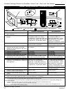
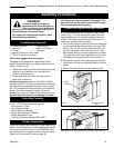
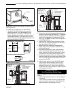
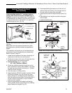
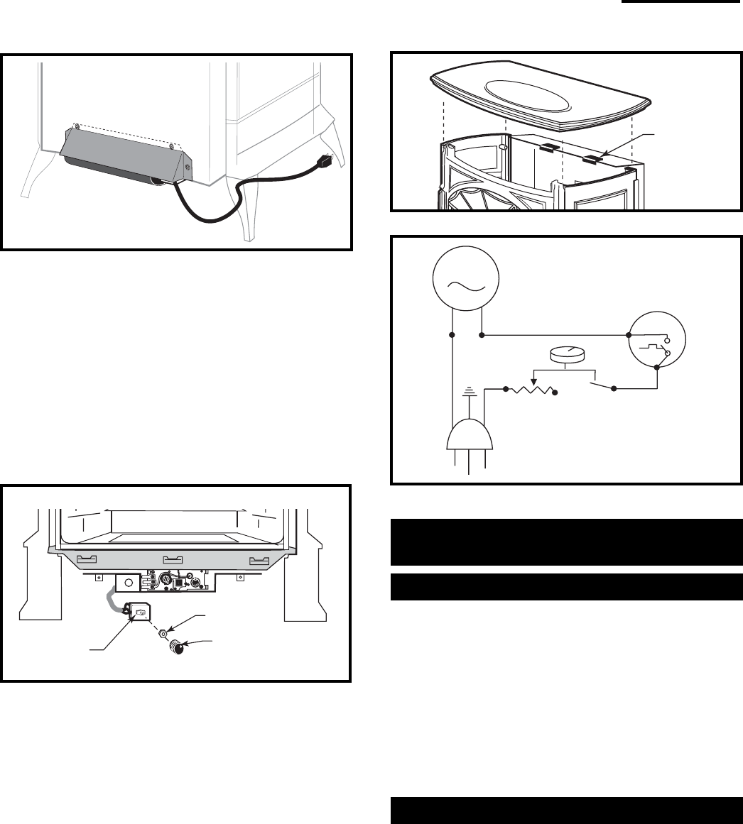
4. The rheostat control switch attaches to the left side of
the valve bracket at the front of the stove. (Fig. 20)
• Remove the plug from the rheostat bracket.
• Insert the switch box shaft through the hole in the
back of the right side of the valve bracket, aligning
the locator pin with the smaller hole in that bracket.
• Attach the retaining nut to the switch control shaft
to secure it to the plate.
• Attach the Control Knob to the rheostat shaft.
• Use the wire tie to secure the fan and rheostat
wire harnesses together.
Rheostat
Retaining Nut
Rheostat Knob
FK104
Fig. 20 Attach rheostat to bracket.
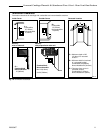
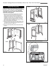
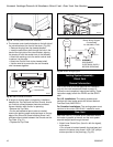
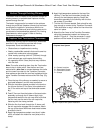
5. A length of silicone tape is included for installation
between the Top Plate and the Rear Shroud, should
you find that contact between these two surfaces
causes vibration while the fan is operating.
• Remove the Top Plate.
• Cut the self-adhesive tape to size as needed,
remove the backing paper and place tape on the top
edge of the Shroud at those locations where it will
eliminate direct contact between the Shroud and the
Top Plate. (Fig. 21)
• Replace the Top Plate.
ST241
Fig. 19 Correct position of fan skirt installation.
Venting System Assembly -
Direct Vent
General Information
The PDV20 and SDVR are approved for installation
only with the vent components listed on page 13.
Follow the vent component instructions exactly. These
instructions apply to both the PDV20 and the SDVR
shell.
For U.S. installations: The venting system must
conform with local codes and/or the current National
Fuel Gas Code, ANSI Z223.1
For Canadian installations: The venting system must
conform to the current CSA B149.1 installation code.
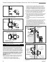
Rear Vent
Use Rear Vent Kit 7TFSRSK for an installation where
the heater is parallel to the wall and the vent system
extends straight back through that wall.
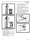
1. Attach Inner Starter Pipe, (found in with the logset),
to the stove.
• Run a bead of sealant beneath the pipe bead and
attach to the stove using three 1/4-20 x 3/8” phillips
screws provided in the parts bag. (Fig. 23)
Cut pad to size
and locate as
needed
FK105
Fig. 21 Vibration dampening pad location.
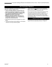
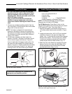
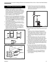
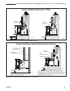
MOTOR
SNAPSTAT
ON/OFF
RHEOSTAT
WHT
WHT
BLK
BLK
BLK
GRN
BLK
Blower Wiring Diagram
Fan Assembly
No. 000-2960 / FK28
WARNING:
DISCONNECT
ELECTRICAL SUPPLY
BEFORE SERVICING
Fig. 22 Blower wiring diagram.