


21
Vermont Castings Jefferson Direct Vent/Natural Vent Gas Heater
20002191
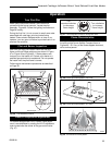
Connect the Gas Supply Line
Check the Rating Plate attached by a steel cable to the
firebox, to confirm that you have the appropriate firebox
for the type of fuel to be used. The Jefferson may be
converted from one gas to another using the appropri-
ate Fuel Conversion Kit listed on page 34.
In the U.S.; Gas connection should be made in accor-
dance with current National Fuel Gas Code, ANSI
Z223.1. Since some municipalities have additional local
codes, be sure to consult you local authority.
In Canada; consult the local authority and CSA-B149.1
installation code.
Always check for gas leaks with a mild
soap and water solution. Do not use an
open flame for leak testing.
Light the pilot according to the directions on page 26,
before going to the next step.
This appliance should only be
connected by a qualified gas techni-
cian. Test to confirm manifold
pressures as specified below.
The Jefferson Heater and its individual shutoff
valve must be disconnected from the gas supply
piping during any pressure testing of that system
at test pressures in excess of 1/2 psig (3.5 kPa).
The Jefferson Heater must be isolated from the
gas supply piping system by closing its indi-
vidual manual shutoff valve during any pressure
testing of the gas supply piping system at test
pressure equal to or less than 1/2 psig.
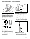
There must be a gas shutoff between the stove
and the supply.
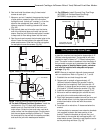
In order to connect Natural Gas, use a fitting with
3/8” NPT nipple on the valve side and 1/2” natural
gas supply line with an input of 28,000 BTUs at a
manifold pressure of 3.5” and minimum inlet
supply for adjustment of 5.5” w.c.
In order to connect Propane, use a fitting with 3/
8” NPT nipple on the valve side and 1/2” propane
gas supply line with an input of 28,000 BTUs at a
manifold pressure of 10.0” and minimum inlet
supply for adjustment of 11.0” w.c.
CAUTION
Burner Information
The appliance must only use the gas specified on the
rating plate, unless converted using a Vermont Cast-
ings Fuel Conversion Kit. To convert from LP to Natural
Gas use Kit #000-5021. To convert from Natural Gas to
LP use Kit #000-5022.
Conversion instructions are provided with each kit and
beginning on Page 28 in this manual.
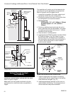
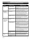
Air Shutter Adjustment
The Jefferson is shipped from the factory with the air
shutter adjusted to the minimum allowed opening.
Refer to Table 1. Based on the altitude where the stove
is located, a shutter adjustment is acceptable to provide
a mixed balance of flame color/glow. To adjust the
shutter opening, follow the steps below.
NOTE: The air shutter may only be adjusted to a more
open position. The factory setting is the minimum
allowable air shutter opening.
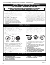
THIS APPLIANCE SHOULD BE CONNECTED
TO THE GAS SUPPLY ONLY BY A QUALIFIED
GAS SERVICE TECHNICIAN. FOLLOW ALL
LOCAL CODES.
THERE MUST BE A GAS SHUT-OFF BE-
TWEEN THE STOVE AND THE SUPPLY.
Model Natural Gas LP
Direct Vent ¹⁄₂” ¹⁄₂”
Natural Vent ¹⁄₂”1”
Table 1. Air Shutter Adjustment
Minimum rear injector air inlet openings.
In order to connect Natural Gas, use a fitting with 3/8”
NPT nipple on the valve side and 1/2” natural gas
supply line with an input of 28,000 BTUs at a manifold
pressure of 3.5” and minimum inlet supply for adjust-
ment of 5.5” w.c.
In order to connect Propane, use a fitting with 3/8”
NPT nipple on the valve side and 1/2” propane gas
supply line with an input of 28,000 BTUs at a manifold
pressure of 10.0” and minimum inlet supply for adjust-
ment of 11.0” w.c.
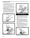
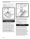
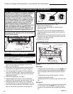
Air Shutter Adjustment Instructions
To adjust the air shutter, the following procedures
should be followed:
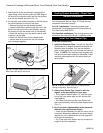
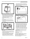
1. Remove stove front. Lift stove front up and then
swing bottom out and away to disengage from the
stove body. (Fig. 37)
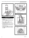
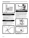
2. Swing open the swiveling latches at the top left and
right corners of the glass frame. (Fig. 12, Page 13)