


10
Dutchwest Non-Catalytic Convection Heater
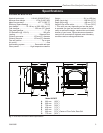
30003850
Clearances
As with any solid fuel heating stove, extremely high
surface temperatures can occur, particularly in the
event of uncontrolled operation, e.g. if the doors
are inadvertently left open. It is crucial that suf-
ficient clearances are allowed to any combustible
surfaces, e.g. wooden mantels or lintels, and to
timber framed (studded) walls even if they are faced
with noncombustible board. Detailed information
on fireplace and hearth construction is provided
in section 2 of Document J, all installations must
comply with these requirements or with the relevant
National or local building standards.
Clearances to timber framed (studded) walls are includ-
ed below. There are no specific minimum clearances
to solid noncombustible, surfaces (e.g. the sides and
rear of Inglenook fire openings constructed from solid
masonry) other than to allow safe access to the controls
of the stove. For this reason minimum side clearances
of 125 mm, and a minimum rear clearance of 50 mm
are recommended.
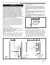
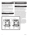
Summary of Clearances
Minimum recommended side clearances to non-
combustible surfaces 125 mm (5”).
Minimum recommended rear clearance to noncom-
bustible surfaces 50 mm (2”).
NOTE: The minimum thickness of solid noncombustible
materials is specified in section 2 of Document ‘J’, in
relation to the clearance of the appliance from the sur-
face. As a general rule, the thickness of solid noncom-
ST486a
Defiant EU
Clearance
Diagrams
10/06
A
B
ST486a
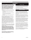
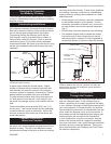
Fig. 13 Minimum clearances.
bustible material forming the recess of a fireplace is a
minimum of 200 mm.
Minimum rear clearance from combustible walls
(e.g. timber framed or studded walls) 660 mm (26”)
measured from the rear edge of the stove top. (Fig.
13, B)
Minimum side clearance from combustible walls
600 mm (23⁵⁄₈”) measured from the side edge of the
stove top. (Fig. 13, A)
Minimum distance from stove to movable combus-
tible materials (e.g. furniture, drying clothes, etc.)
1220 mm (48”).
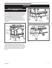
D
at least
3 x D
Elevation
Without
Shield
Elevation
With Shield
at least
3 x D
at least
1.5 x D
at least 1.5
x D
Plan Without
Shield
Plan With
Shield
Air space of at least 12 mm
between noncombustible shield
and combustible material
Fluepipe
at least
1.5 x D
at least
1.5 x D
at least 3 x D
D
at least
1.5 x D
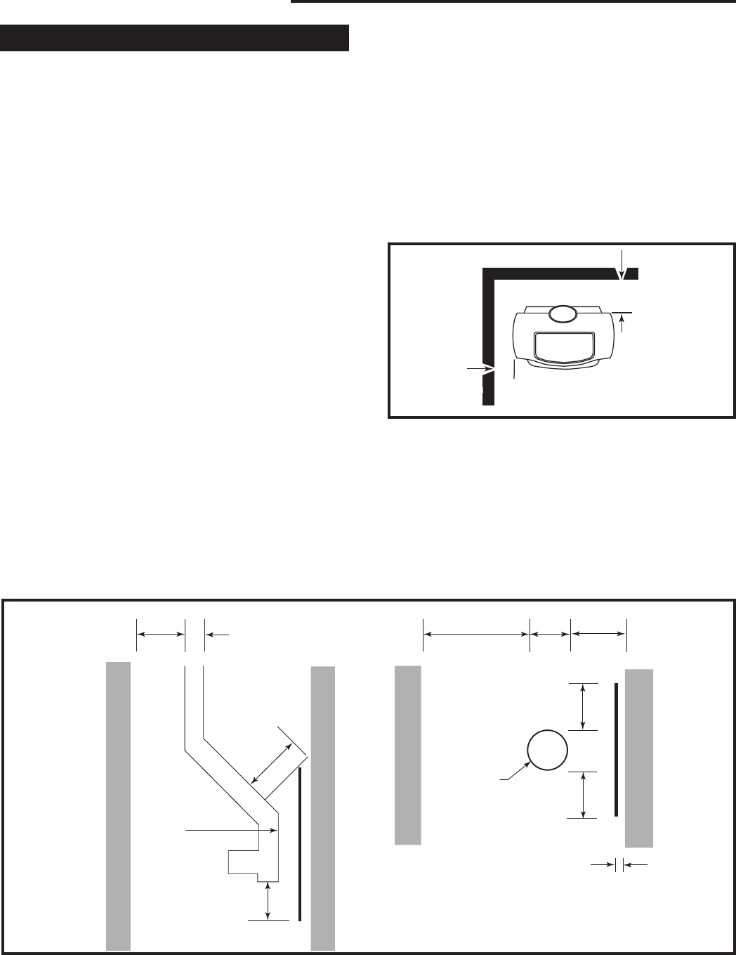
ST911
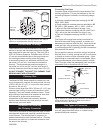
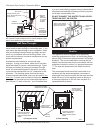
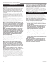
Fig. 14 Connecting fluepipe clearances.
Connecting Flue Pipe - Clearances
Single wall connecting fluepipes can reach extremely
high temperatures; therefore, clearances from the con-
necting fluepipe (chimney connector) must comply with
the requirements of Part J of Building Regulations 2000
(Combustion Appliances and Fuel Storage Systems).
This can be achieved by following the recommenda-
tions of Approved Document ‘J’. These are as shown in
Figure 14.