


E-27
Assembly Instructions
IMPORTANT!
• Be sure to assemble the stand on a flat surface.
• This stand does not include any of the tools required to
assemble it. You should have a large Phillips head (+)
screwdriver on hand for assembly.
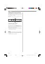
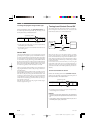
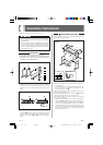
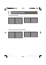
Figure 1
• Check the items that come with the unit to make sure that
everything shown in Figure 1 (A through L) is included.
All screws are in a plastic bag inside of the packing card-
board.
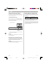
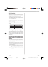
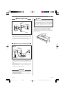
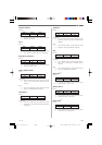
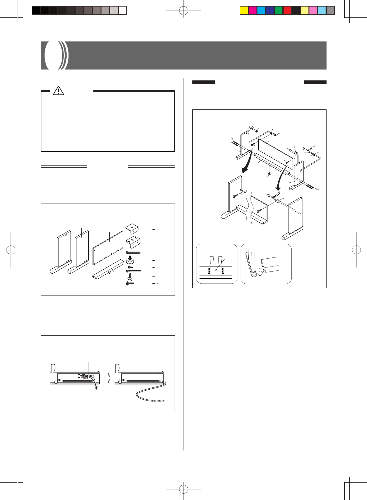
Figure 3
1.Attach E brackets to side uprights A and B using the I
screws (Figure 3).
• When attaching the E bracket to the side upright B, slip
a J clip onto the I screw before screwing the I screw
into the upright at point 3.
2.Attach angle brackets F to side uprights A and B using
the four I screws (Figure 3).
3.Install height adjustment screw H into hole 4 located in
the center of the back of crosspiece D (Figure 3).
4.Attach side uprights A and B to crosspiece D using the
four G screws (Figure 3).
• Make sure that crosspiece D is correctly positioned as
indicated by 5 in the inset of Figure 3. It should be per-
pendicular (at a 90-degree angle) to the two side uprights.
Also make sure that uprights A and B are parallel with
each other. If the pieces are not positioned correctly, the
nuts built into crosspiece D will not seat properly with
the G screws. This can result in stripping of the threads
and free turning of nuts.
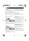
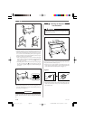
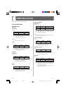
Figure 2
• Before starting actual assembly of the stand, undo the clip
at location 1 (Figure 2) where the pedal cable comes out
the back of crosspiece D. Pull out the coiled cable and re-
fasten two clips at points 1 and 2 as shown in the illus-
tration.
1 Assembling the stand
Refer to Figures 3, 4 and 5 as you assemble the stand accord-
ing to the following procedure.
x4
x2
x1
x14
x2
x2
G
F
H
I
J
K
A
B
C
D
Lx2
x2 E
21
G
A
H
D
B
G
F
I
C
F
I
*
*
E
I
J
I
3
L
L
E
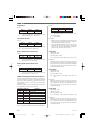
5
Side upright
Crosspiece
Bottom
4
Caution
• Take particular care to avoid injury when installing
legs and pedals, and when mounting the keyboard
onto the stand.
• When assembling, make sure that the sliding keyboard
cover of the piano body is completely closed. If the
cover is left open during assembly, it may close sud-
denly causing the fingers to be pinched between the
piano body and cover.
• Illustrations in this User’s Guide shows the AP-31.
427B-E-031A
AP31/33_E_26_30.p65 03.10.22, 5:05 PMPage 27 Adobe PageMaker 6.5J/PPC