


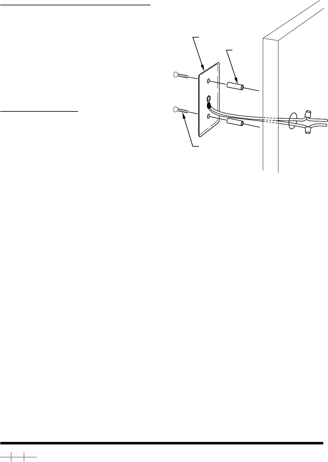
IF PLATE IS ATTACHED DIRECTLY TO WALL: (See Fig. 2.)
Drill a suitable hole through the wall at selected sensor location.
Route sensor wires through wall, making sure they are accessible
from the inside. Use provided spacers to stand off plate from wall.
Mount the sensor plate loosely to wall with only 1 screw so that
access to hole is preserved for application of caulking. Fill hole
with a suitable exterior caulking compound. Then insert second
screw and tighten both screws carefully.
From inside, locate sensor wires and wires from thermostat. Cut
and trim thermostat wires to an appropriate length and connect
with supplied wire nuts. It may be advisable to retain thermostat
wire with a clamp or wire staple ahead of wire nuts to prevent a
pull on this wire from damaging the more delicate sensor connec-
tions.
THERMOSTAT CONNECTION:
Turn OFF all power to system. The thermostat display will go
blank. Open thermostat at rear hinge to access connector blocks.
Route and connect wires at thermostat carefully to minimize
amount of wire between wall and thermostat. Strip ends only 1/4
in. to prevent a possible short between wires at the thermostat.
Attach wires to S1 and S2 terminals. Polarity is unimportant.
Route wires behind thermostat so that hinge can close properly.
When wiring is completed and thermostat closed, restore power to
system. Refer to Homeowners manual for procedure to display
remote temperature.
SENSOR
WOOD SCREWS
SPACERS EXTERIOR
WALL
A94410
Fig. 2—Mounting Directly to Wall
Copyright 1994 CARRIER Corp. • 7310 W. Morris St. • Indianapolis, IN 46231 tstat3si
Manufacturer reserves the right to discontinue, or change at any time, specifications or designs without notice and without incurring obligations.
Book 1 4
Tab misc. misc.
PC 101 Catalog No. 92-33TS-TA13C Printed in U.S.A. Form TSTAT-3SI Pg 2 12/15/94 Replaces: New