


7
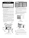
NOTE: For 14K to 23K models, the bottom channel has been
factory--installed, and their shapes may differ from the others, but
their functions are similar.
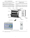
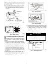
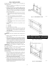
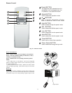
Step 4 —Assembly of the side shutters (curtains) to the cabinet.
A. Slide the shutters into the top and bottom channels as shown in
Fig. 9. The s hutters are identified (on each frame) as ”left” &
”right”. Attach the shutters to the cabinet using (4) 1/4” screws
on each side.
For 10K to 12K models
Channel
1/4" Screw
Double
Adhering seal
For 14K to 23K models,
( Factor
y
-Installed)
A06537
Fig. 8 --- Channel Assembly
Shutter Frame
Right Shutte
r
1/4" screw
A06538
Fig. 9 --- Shutter Assembly
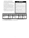
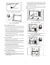
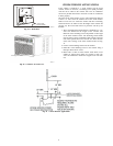
Step 5 —Installation of Mounting Brackets and First Sealing
Strip
NOTE: Windows come in a variety of different styles. Therefore,
it may be necessary to modify or improve your particular
installation.
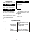
A. Attach the bracket assembly to 90 angle support brackets (Fig.
10) using (2) 1 1/2” bolts, two bolts per bracket. Secure with
the (2) 1/4” lock washers and (2) 1/4”nuts. DO NOT
immediately tighten these bolts as it may be necessary to adjust
the depth of the bracket assembly, depending on the depth of
your window sill. See (Fig. 12).Install the two leveling screws
into the 90 support brackets. Test the bracket assembly in the
window before cabinet installation. If the leveling screws are
distanced too far away from the wall to provide stability, it may
be necessary for you to fill this area with a solid piece of wood.
See (Fig. 13).
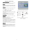
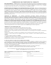
B. Measure the inside window sill width and find the center as
shown in (Fig. 11). Align the V--slot in each bracket on these
marks and mount the brackets to the sill using 3/4” screws
provided. Brackets should be perpendicular to the inside
window sill. See (Fig. 11).
Bracket Assembly
Bracket Bolts
Leveling Screw
V-slot
90 Angle
Support Brackets
(TOP VIEW)
A06539
Fig. 10 --- Bracket Assembly
Center
Window sill
V-slot
Measurement for Model 10K =9.6"
9.6"
9.6"
Measurement for Model 12K = 10.3"
10.3"
10.3"
12.6"
12.6"
Measurement for Model 14K to 23K = 12.6"
A06540
Fig. 11 --- Bracket Mounting
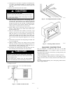
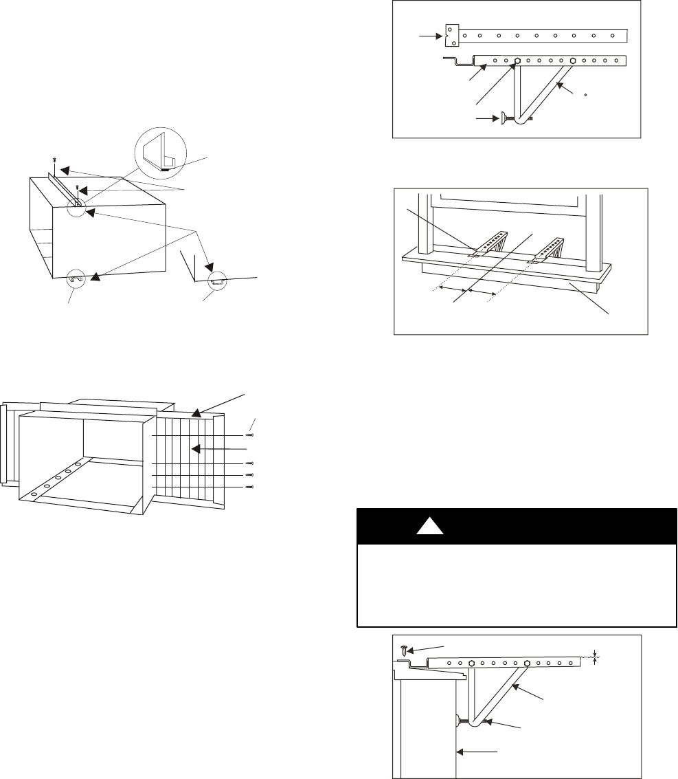
C. For proper condensation run--off it will be necessary to adjust
the angle/pitch of the window brackets. This is accomplished
by adjusting the distance of the leveling screw on the outer
wall. The maximum angle/pitch should not exceed more than
3/16”. See (Fig.12).
D. Cut the seal strip to fit the underside of the bottom window
sash. Remove the peel--off backing on t he seal and attach it to
this sash. See (Fig. 14).
UNIT DAMAGE HAZARD
Failure to follow this caution may result in unit damage.
Use a solid piece of wood to provide stability. This will be
required when sills are extra deep (see Fig. 13).
CAUTION
!
(2) 3/4" screws per bracket
Bracket Assembly
Leveling Screw
Outer Wall Construction
3/16" Maximum
A06541
Fig. 12 --- Depth/Angle Illustration