


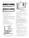
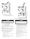

bracket and ignitor assembly to bottom of burner box. The
screw in the bracket is always located toward outside of
burner box. The screw may be hidden by inlet box or inlet
pipe, but can be removed without removing either. After
removing screw, slide ignitor and bracket toward outside of
burner box and pull straight out.
The ignitor is fragile. DO NOT allow it to hit the side of the
burner box opening while removing or replacing it.
b. Inspect ignitor for a white area indicating a crack may be
present. If found, replace ignitor.
NOTE: A small crack cannot be seen on a new ignitor. After a
period of operation, a white area will be visible around the crack.
c. If replacement is required, replace ignitor on ignitor bracket
external to furnace to avoid damage as the silicon portion is
very brittle and will easily crack or shatter.
d. To remove ignitor from ignitor bracket, remove screw
holding ignitor ceramic block to bracket and pull ceramic
block out of bracket.
6. To replace ignitor/ignitor assembly, reverse items 5a through
5d.
7. Reconnect ignitor wire connection.
8. Turn on gas and electrical supplies to furnace.
9. Verify ignitor operation by initiating control board self-test
feature or by cycling thermostat.
10. Replace main furnace door.
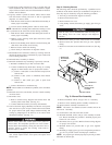
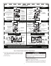
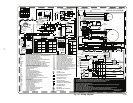
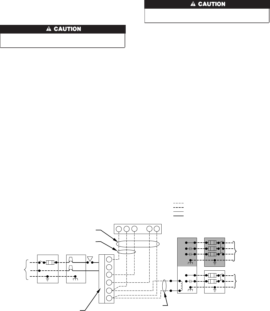
Step 7—Electrical Controls and Wiring
There may be more than 1 electrical supply to the unit. Check
accessories and cooling unit for additional electrical supplies.
The electrical ground and polarity for 115-v wiring must be
maintained properly. Refer to Fig. 11 for field wiring information
and to Fig. 15 for unit wiring information.
NOTE: If the polarity is not correct, the STATUS LED on the
control center will flash rapidly and prevent the furnace from
operating. The control system also requires an earth ground for
proper operation of the control center and flame sensing.
The 24-v circuit contains an automotive-type, 3-amp fuse located
on the control center. (See Fig. 12.) Any direct shorts of the 24-v
wiring during installation, service, or maintenance will cause this
fuse to blow. If fuse replacement is required, use ONLY a fuse of
identical size.
With power to the unit disconnected, check all electrical connec-
tions for tightness. Tighten all screws on electrical connections. If
any smoky or burned connections are found, disassemble the
connection, clean all parts, strip wire, and reassemble properly and
securely.
Reconnect electrical supply to unit and observe unit through 1
complete operating cycle. Electrical controls are difficult to check
without proper instrumentation; if there are any discrepancies in
the operating cycle, contact your dealer and request service.
Step 8—Checking Heat Tape Operation
(If Applicable)
In applications where the ambient temperature around the furnace
is 32°F or lower, freeze protection measures are required. If this
application is where heat tape has been applied, check to ensure it
will operate when low temperatures are present.
Fig. 11—Field Wiring
A98325
115-V
FIELD-SUPPLIED
DISCONNECT
SWITCH
115-V
SINGLE
PHASE
AUXILIARY
J-BOX
FURNACE
CONTROL
CENTER
TWO WIRE
24-V
TERMINAL
BLOCK
THREE-WIRE
HEATING
ONLY
FIVE
WIRE
NOTE 5
NOTE 1
NOTE
3
THERMOSTAT
TERMINALS
FIELD-SUPPLIED
DISCONNECT
CONDENSING
UNIT
R
W2
WCR GY
GND
GND
GND
GND
FIELD 24-V WIRING
FIELD 115-, 208/230-, 460-V WIRING
FACTORY 24-V WIRING
FACTORY 115-, 208/230-, 460-V WIRING
208/230- OR
460-V
THREE PHASE
208/230-V
SINGLE
PHASE
W/W1
Y/Y2
G
C
NOTES:
1.
2.
3.
4.
5.
Connect Y or Y/Y2 terminal as shown for proper cooling operation.
Proper polarity must be maintained for 115-v wiring.
Use W2 with 2-stage thermostat when zoning.
If any of the original wire, as supplied, must be replaced, use
same type or equivalent wire.
Some thermostats require a "C" terminal connection as shown.
8