


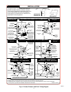
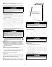
Allow ignitor to cool before removal. Normal operation
temperatures exceed 2000°F.
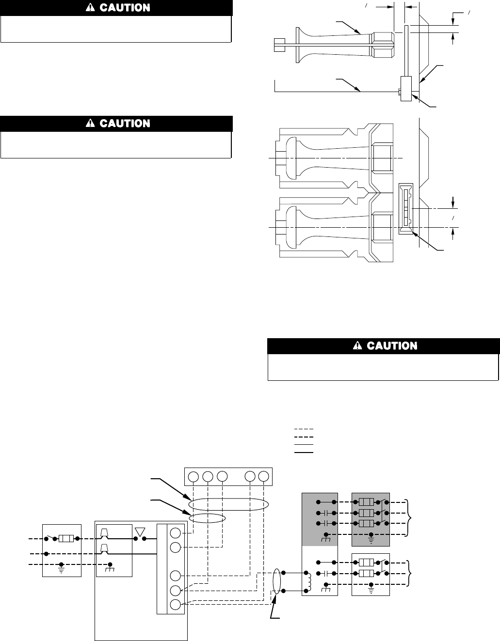
a. Do not remove ignitor from retainer while assembly is in
furnace. Using a small pocket straight-blade screwdriver,
slowly pry 1 edge of the spring retainer from burner box
housing. While working ignitor assembly loose, grasp
white ceramic block to wiggle assembly (ignitor and
retainer) from its location.
The ignitor is fragile. DO NOT allow it to hit the side of the
burner box opening while removing or replacing it.
b. Inspect ignitor for a white area indicating a crack may be
present. If found, replace ignitor.
NOTE: A small crack cannot be seen on a new ignitor. After a
period of operation, a white area will be visible around the crack.
c. If replacement is required, replace ignitor on ignitor re-
tainer external to furnace to avoid damage as the silicon
portion is very brittle and will easily crack or shatter.
d. To remove ignitor from ignitor retainer, apply pressure on
bottom/side clips to release pressure on ignitor ceramic
block. Slowly work ceramic block out of spring retainer.
6. To replace ignitor/ignitor assembly, reverse items 5a through
5d. (See Fig. 11.)
7. Reconnect ignitor wire connection.
8. Turn on gas and electrical supplies to furnace.
9. Verify ignitor operation by initiating control board self-test
feature or by cycling thermostat.
10. Replace main furnace door.
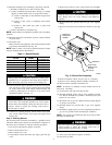
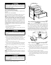
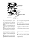
Step 7—Electrical Controls and Wiring
There may be more than 1 electrical supply to the unit. Check
accessories and cooling unit for additional electrical supplies.
The electrical ground and polarity for 115-v wiring must be
maintained properly. Refer to Fig. 12 for field wiring information
and to Fig. 16 for unit wiring information.
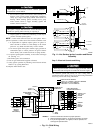
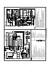
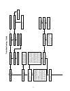
→ Fig. 12—Field Wiring
A96415
115-VOLT FUSED
DISCONNECT
SWITCH
(WHEN
REQUIRED)
AUXILIARY
J-BOX
CONTROL
BOX
24-VOLT
TERMINAL
BLOCK
THREE-WIRE
HEATING-
ONLY
FIVE
WIRE
NOTE 1
NOTE 2
FIELD-SUPPLIED
FUSED DISCONNECT
CONDENSING
UNIT
TWO
WIRE
FURNACE
R
G
C
WCR GY
GND
GND
FIELD 24-VOLT WIRING
FIELD 115-, 208/230-, 460-VOLT WIRING
FACTORY 24-VOLT WIRING
FACTORY 115-VOLT WIRING
208/230- OR
460-VOLT
THREE
PHASE
208/230-
VOLT
SINGLE
PHASE
WHT
BLK
WHT
BLK
NOTES: Connect Y-terminal as shown for proper operation.
Some thermostats require a "C" terminal connection as shown.
If any of the original wire, as supplied, must be replaced, use
same type or equivalent wire.
W
Y
GND
THERMOSTAT
TERMINALS
1.
2.
3.
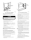
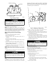
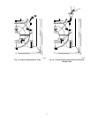
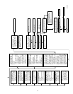
Fig. 11—Hot Surface Ignitor Location and Burner
Assembly
A93260
BURNER
IGNITOR
13
32
"
11
32
"
7
8
"
C
L
C
L
IGNITOR
ASSEMBLY
IGNITOR
ASSEMBLY
CELL
PANEL
BURNER
BURNER BOX
8