


2
SAFETY CONSIDERATIONS
Installationand servicingofthisequipmentcanbehazardousdueto
mechanical and electrical components. Only trained and qualified
personnel should install, repair, or service this equipment.
Untrained personnelcanperformbasicmaintenancefunctionssuch
as cleaning and replacing air filters. All other operations must be
performed by trained service personnel. When working on this
equipment,observe precautions inthe literature, on tags, and on la-
belsattachedtoorshippedwiththeunitandothersafetyprecautions
that may apply.
Follow all safety codes. Installation mustbein c ompliance with lo-
cal and national building codes. Wear safety glasses, protective
clothing, and work gloves. Have fire extinguisher available. Read
these instructions thoroughly and follow all warnings or cautions
included in literature and attached to the unit.
Recognize safety information. This is the safety --alert symbol
!
!
Whenyouseethissymbolontheunitandininstructionsormanuals,
be alert to the potential for personal injury.
Understandthesesignalwords:DANGER,WARNING,andCAU-
TION. These words are used with the safety--alert symbol. DAN-
GER identifies the most serious hazards which will result in severe
personalinj uryordeath.WARNING signifieshazardswhichcould
resultinpersonalinjuryordeath.CAUTIONisusedto identifyun-
safepracticeswhichmayresultinminorpersonal injuryorproduct
andpropertydamage.NOTEisusedtohighlightsuggestionswhich
will result in enhanced installation, reliability, or operation.
Note:Installer:This manualshouldbeleftwiththeequipment user.
ELECTRICAL SHOCK AND OPERATION HAZARD
Failureto follow thiswarning could resultin personalinjury,
death or property damage.
Do not use this unit if any part has been underwater.
Imme diately call a qualified service technician to inspect the
unit and to replace any part of the control system which has
been underwater.
!
WARNING
ELECTRICAL SHOCK AND CUT HAZARD
Failureto follow thiswarning could resultin personalinjury,
death or property damage.
When removing access panels or performing maint enance
functionsinsideyourunit,beawareofsharpsheetmetalparts
and screws. Although special care is taken to reduce sharp
edges to a minimum, be extremely careful when handling
parts or reaching into the unit.
!
WARNING
TO START UNIT:
1. Turn on the electrical power supply to the unit.
2. Select temperature and set system switch to desired mode.
TO SHUT OFF UNIT:
Note: If the uni t is being shut down because of a malfunction, call
your dealer as soon aspossible.
1. Setthe temperature switch to OFF.
2. Turn off the electrical power supply to unit.
ROUTINE MAINTENANCE
Allroutinemaintenanceshouldbe handledby skilled,experienced
personnel.Yourdealercanhelp youestablish astandardprocedure.
For your safety, keep the unit area clear and free of combustible
materials, gasoline, and other flamma ble liquids and vapors.
To assureproperfunctioning oftheunit,flowofcondenserairmust
not be obstructed from reaching the unit. Clearancefromthe top of
the unit is 48 in. (1219 mm). Clearanceof atleast 36 in. (914 mm)
is required on sides except the power entry side (42 in. [1067 mm]
clearance) andtheductside(12in.[305mm]minimum clearance).
Maintenance and Care for the Equipment Owner
Before proceeding with those things you might want to maintain
yourself, please carefully consider the following:
FIRE, EXPLOSION, ELECTRICAL SHOCK AND
CUT HAZARD
Failureto follow thiswarning could resultin personalinjury,
death or property damage.
1. TURN OFF ELECTRICAL POWER TO YOUR UNIT
BEFORE SERVICING OR PERFORMING
MAINTENANCE.
2. Whenremoving accesspanels orperforming maintenance
functions inside your unit, be aware of sharp sheet metal
parts and screws. Although special care is taken to reduce
sharp edges to a m inimum, be extremely careful when
handling parts or reaching into the unit.
!
WARNING
Air Filters
Theairfilter(s) shouldbechecked every3 or4 weeks andchanged
or cleaned whenever it becomes dirty. Dirty filters produce exces-
sivestressontheblowermotorandcancausethemotorto overheat
and shut down.
This unit must have air filters in place before it can be operated.
These filters can be located in one of at least two places. In many
applications, the installer will pr ovide return air filter grilles
mounted on the wall or ceiling of the conditioned structure. In the
instance of filter grilles, the f ilters can simply beremoved from the
grille and replaced.
The other typical application is an accesso ry filter rack installed
inside the unit itself. The following information is given to assist
in changing filters used in these internal filter racks.
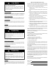
Table 1 indicates the correct indoor filter size for your unit.
Table 1—Indoor Air Filter Data
Unit Size Filter Size
024---036 24x24x1 (610x610x25 m m)
042---060 30x30x1 (762x762x25 m m)
If you have difficulty locating your air filter(s) or have questions
concerning proper filter maintenance, cont act your dealer for
instructions. When replacing filters, always use the s ame size and
type of filter that was s upplied, originally, by the installer.