


Step 4—Defrost Mode
When your heat pump is providing heat to your home or office and
the outdoor temperature drops below 45°F/7.2°C, moisture may
begin to freeze on the surface of the coil. If allowed to build up,
this ice would impede airflow across the coil and reduce the
amount of heat absorbed from the outside air. So, to maintain
energy-efficient operation, your heat pump has an automatic
defrost mode.
The defrost mode starts at a factory selected interval of 30 minutes,
although, it may be reset to 50 or 90 minutes. Defrost will start at
the preset time only if the ice is sufficient to interfere with normal
heating operation.
After the ice is melted from the coil, or after a maximum of 10
minutes in defrost mode, these units automatically switch back to
normal heating operation.
Do not be alarmed if steam or fog appears at the outdoor unit
during defrost mode. Water vapor from the melting ice may
condense into a mist in the cold outside air.
During certain weather conditions such as heavy snow and
freezing rain it is not uncommon for ice to build up on the unit
grille. This is normal for these weather conditions. Do not attempt
to remove the ice from the unit grille. This condition will not affect
the proper function of the unit and will clear within a few days.
Step 5—Emergency Heat Mode
This allows your supplemental heating source to keep your home
or office warm until your heat pump can be serviced.
MAINTENANCE AND SERVICE
This section discusses maintenance that should be performed by
your dealer and with care you, as the owner, may wish to handle
for your new heat pump.
ROUTINE MAINTENANCE
All routine maintenance should be handled by skilled, experienced
personnel. Your dealer can help you establish a standard proce-
dure.
For your safety, keep your unit area clear and free of combustible
materials, gasoline, and other flammable liquids and vapors.
To assure proper functioning of your unit, flow of condenser air
must not be obstructed from reaching the unit. Minimum clearance
from the top of the unit is 48 in./1219 mm. Clearance of at least 36
in./914 mm is required on sides except the power entry side (42
in./1067 mm clearance) and the duct side (12 in./305 mm mini-
mum clearance).
MAINTENANCE AND CARE FOR THE EQUIPMENT
OWNER
Before proceeding with those things you might want to maintain
yourself, please carefully consider the following:
1. TURN OFF ELECTRICAL POWER TO YOUR UNIT
AND INSTALL LOCK-OUT TAG BEFORE SERVIC-
ING OR PERFORMING MAINTENANCE. ELECTRIC
SHOCK COULD CAUSE SERIOUS INJURY OR
DEATH.
2. When removing access panels or performing maintenance
functions inside your unit, be aware of sharp sheet metal
parts and screws. Although special care is taken to keep
sharp edges to a minimum, be extremely careful when
handling parts or reaching into the unit.
Air Filters
The air filter(s) should be checked at least every 3 or 4 weeks and
changed or cleaned whenever it becomes dirty. Dirty filters
produce excessive stress on the blower motor and can cause the
motor to overheat and shut down. Table 1 indicates the correct
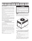
filter size for your unit. Refer to Fig. 2 to access the filters.
To replace or inspect filters (or accessory filter rack when
supplied):
1. Remove the filter access panel using a 5/16-in. (7.9 mm) nut
driver or wrench.
2. Remove the filter(s) by pulling it out of the unit. If the filter(s)
is dirty, clean or replace with a new one.
When installing the new filter(s), note the direction of the airflow
arrows on the filter frame.
If you have difficulty locating your air filter(s) or have questions
concerning proper filter maintenance, contact your dealer for
instructions. When replacing filters, always use the same size and
type of filter that was supplied, originally, by the installer.
Table 1—Indoor-Air Filter Data
UNIT SIZE
50JS (50HZ)
024 030 036 048 060
RETURN-AIR
FILTERS (mm.)
Throwaway
20” x 20”
(508 x 508)
20” x 20”
(508 x 508)
20” x 24”
(508 x 609.6)
24” x 30”
(609.6 x 762)
24” x 30”
(609.6 x 762)
Fig. 2—Filter Access Panel-Vertical Supply Shown
(Unit Shown with Optional Louvered Grille)
C99094
ACCESS PANEL
FILTER ACCESS
PANEL*
*For accessory filter rack.
2