


3
sorbedfromtheoutsideair.So,tomaintainenergy--efficient opera-
tion, yourunit hasan automatic defrost mode.
The defrost mode starts at a preset time interval of 60 minutes, al-
though, it may be reset to 30, 90 or 120minutes. Defrost will start
atthepresettimeonlyiftheiceissufficienttointerferewithnormal
heating operation.
After the iceismelted from the coil,or aftera maximum of 10 min-
utesindefrostmode,theunitautomaticallyswitchesbacktonormal
heating operation.
Donotbealarmedifsteamorfogappearsattheoutdoorunitduring
defrost mode. Water vapor from the melting icemay c ondenseinto
a mist in the cold outside air.
During certain w eatherconditionssuchas heavy snow andfreezing
rain itis not uncommon for iceto build up on theunit grille. Thisis
normalfortheseweatherconditions. Do notattempt to removethe
ice from the unit grille. This condition will not affect the proper
function of theunit and will clear within afew days.
Emergency Heating Mode
In the event ofprimary unit heat failure, the emergency heatmode
allowsyour supplementalheating source tokeep yourhome orof-
ficewarmuntilyourunitcanbeserviced. Contactyourdealerinthe
event of primary unit heat failure.
MAINTENANCE AND SERVICE
This section discusses maintenance that should be performed by
yourdealerandcareyou,astheowner,maywishtohandleforyour
new unit.
Routine Maintenance
Allroutinemaintenanceshouldbe handledby skilled, ex perienced
personnel.Yourdealercanhelpyouestablishastandardprocedure.
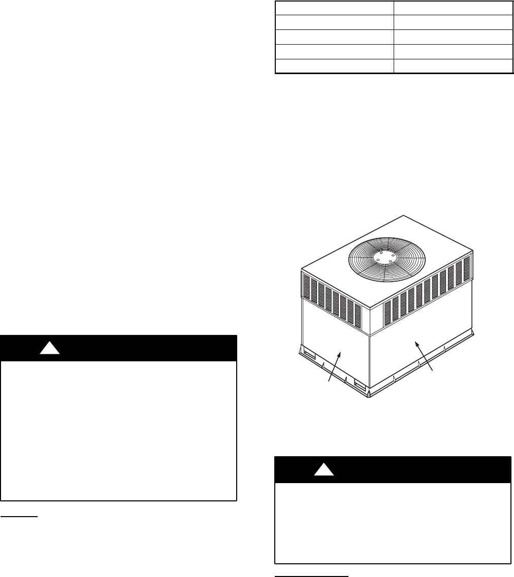
Toassureproperfunctioningoftheunit,flowofcondenserairmust
not be obstructed from reaching the unit.Clearance from t he top o f
the unit is 48 in. (1219 mm). Clearanceof atleast 36 in. (914 mm)
is required on sides except t he power entry side (42 in. c learance)
(1067mm)andtheductside(12in.minimumclearance)(305mm).
Maintenance and Care for theEquipment Owner
Before proceeding with those things you might want to maintain
yourself, pleasecarefully consider the following:
FIRE,EXPLOSION,ELECTRICALSHOCKHAZARD
Failureto follow this warning could result in personalinjury,
death or property damage.
1. TURN OFF ELECTRICAL POWER TO YOUR UNIT
BEFORE SERVICING OR PERFORMING
MAINTENANCEANDINSTALLA LOCK--OUTTAG.
2. Whenremoving accesspanels orperforming maintenance
functions inside your unit, be aware of sharp sheet metal
parts and screws. Although special care is taken to reduce
sharp edges to a minimum, be extremely careful when
handling parts or reaching into the unit.
!
WARNING
Air Filters
The air filter(s)should bechecked every3 or4 weeksandchanged
or cleaned w henever it becomes dirty . Dirty filters produceexces-
sivestresson theblowermotorandcancausethemotortooverheat
and shut down.
This unit must have an air filter in place before it can be operated.
Thesefilters shouldbelocatedinatleastoneoftwoplaces.Inmany
applications, the installer will provide return air filter grilles
mounted on thewall or ceiling of the conditioned structure. In the
instance of filtergrilles, the filters can simply be removed from the
grille and replaced.
The other typical application is an accessory filterrack installed in-
side the unit itself. The following information is given to assist in
changing filters used in these internal filter racks.
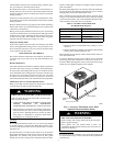
Table 1 indicates the correct indoor filter size for yourunit. Refer
toFig.2 toaccessfiltersinstalledin t heaccessoryfilterrack.Ifusing
an Accessory F ilter Rack, refer to the Installation Instructions pro-
vided with it for correct filter sizes and quantities.
Table 1—Air Filters Located Inside Unit
(For Replacement Purposes)
Unit Size Filter Size in. (mm)
50EZ024 20x20x1 (508x508x25)
50EZ030 20x24x1 (508x610x25)
50EZ036---042 24x30x1 (610x762x25)
50EZ048---060 24x36x1 (610x914x25)
To replace or inspect filters in accessory filter rack:
1. Remove the filter accesspanel (See Fig. 2) using a5/16--in.
nut driver.
2. Removethefilter(s)bypullingitoutoftheunit.Ifthefilter(s)
is dirty, clean or replace with a new one.
Wheninstallingthenew filter(s),notethedirection oftheairflowar-
rows on the filter frame.
If you have difficulty locating your air filter(s) or have questions
concerning proper filter maintenance, contact your dealer for in-
structions.When replacing filters,alwaysusethesamesizeandtype
of filter that was supplied originally by the installer .
ACCESS PANEL
FILTER ACCESS
PANEL*
*For accessory filter rack.
C99094
Fig. 2 -- Accessory Filter Rack Access Panel
(Optional Louvered Panels shown)
FIRE AND UNIT OPERATION HAZARD
Failureto follow this warning could result in personalinjury,
death or property damage.
Never operate your unit without filters in place. An
accumulationofdustandlintoninternalpartsofyourunitcan
cause loss of efficiency.
!
WARNING
Fans and Fan Motor
Periodically check the condition of fan wheels a nd housings and
fan--motorshaftbearings.Contactyourdealerfortherequiredannu-
al maintenance.