


3
CUT HAZARD
Failure to follow this caution may result in personal i njury.
When removing access panels or performing maintenance
functions inside your unit, be aware of sharp sheet metal
parts and screws. Although special care is taken to reduce
sharp edges to a minimum, be extremely careful w hen
handling parts or reaching into the unit.
!
CAUTION
FIRE, EXPLOSION, ELECTRICAL SHOCK
HAZARD
Failure to follow this warning could result in personal
injury, death or property damage.
Do not use this unit if any part has been under water.
Immediately call a qualified service technician to inspect the
unit and to replace any part of the control system which has
been under water.
!
WARNING
Starting or Shutting Unit Off
To start the unit:
1. Turn on the electrical power supply to unit.
2. Select temperature and set MODE control to desired mode.
To shut unit off:
NOTE: If the unit is being shut down because of a malfunction,
call your dealer as soon as possible.
1. Set system MODE control to OFF.
2. Turn off the electrical power supply to unit.
OPERATING YOUR UNIT
The operation of your unit is controlled by indoor thermostat. You
simply adjust the thermostat and it maintains the indoor
temperature at the level you select. Most thermostats of cooling
systems have 3 controls: a temperature control selector, a F AN
control, and a SYSTEM or MODE control. Refer to your
thermostat owner’s manual for more information.
To better protect your investment and to eliminate unnecessary
service calls, familiarize yourself with the following facts:
Cooling Mode
With the SYSTEM or MODE control set to COOL, your unit will
run in cooling mode until the indoor temperature is lowered to the
level you have selected. On extremely hot days, your unit will run
for longer periods at a time and have shorter “off” periods than on
moderate days.
Heating Mode (if installed with optional electric
heat)
Your system may also be equipped with an electric heating source.
On cold days and nights, place your MODE control to HEAT and
your system will automatically turn on the supplemental heat in
order to maintain the level of comfort you have selected.
MAINTENANCE AND SERVICE
This section discusses maintenance that should be performed on
your system. Most maintenance should be performed by your
dealer. You, as the owner, may wish to handle some minor
maintenance for your new unit.
Routine Maintenance
All routine maintenance should be handled by skilled, experienced
personnel. Your dealer can help you establish a standard procedure.
To assure proper functioning of the unit, flow of condenser air
must not be obstructed from reaching t he unit. Clearance from the
top of the unit is 48 in. (1219 mm). Clearance of at least 36 in.(914
mm) is required on sides except the power entry side (42 in. [1067
mm] clearance) and the duct side (12 in. [305 mm] minimum
clearance).
Maintenance and Care for the Equipment Owner
Before proceeding with those things you might want to maintain
yourself, please carefully consider the following:
FIRE, EXPLOSION, ELECTRICAL SHOCK AND
CUT HAZARD
Failure to follow this warning could result in personal
injury, death or property damage.
1. TURN OFF ELECTRICAL POWER TO YOUR UNIT
BEFORE SERVICING OR PERFORMING
MAINTENANCE.
2. When removing access panels or performing
maintenance functions inside your unit, be aware of
sharp sheet metal parts and screws. Although special care
is taken to reduce sharp edges to a minimum, be
extremely careful when handling parts or reaching into
the unit. Wear safety glasses, glove, and appropriate pro-
tective clothing.
!
WARNING
Air Filters
The air filter(s) should be checked every 3 or 4 weeks and
changed or cleaned whenever it becomes dirty . Dirty filters
produce excessive stress on the blower motor and can cause the
motor to overheat and shut down.
This unit must have air filters in place before it can be operated.
These filters can be located in one of at least two places. In many
applications, the installer will provide return air filter grilles
mounted on the wall or ceiling of the conditioned structure. In the
instance of filter grilles, the filters can simply be removed from the
grille and replaced.
The other typical application is an accessory filter rack installed
inside the unit itself. The following information is given to assist in
changing filters used in these internal filter racks.
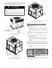
Table 1 indicates the correct indoor filter size for your unit. Refer
to Fig. 3 to access filters installed in the accessory filter rack. If
using an Accessory Filter Rack, refer to the Installation Instructions
provided with it for correct filter sizes and quantities.
Table 1 – Indoor Air Filter Data
Unit Size Filter Size in. (mm)
24 20x20x1 (508x508x25)
30 20x24x1 (508x610x25)
36---42 24x30x1 (610x762x25)
48---60 24x36x1 (610x914x25)
To replace or inspect filters in accessory filter rack (See Fig. 3):
1. Remove the filter access panel using a 5/16--in. nut driver .
2. Remove the filter(s) by pulling it out of the unit. If the
filter(s) is dirty, c lean or replace with a new one.
When installing the new filter(s), note the direction of the airflow
arrows on the filter frame, which should be pointed at the indoor
coil.
3. Reinstall f ilter access panel ensuring opening is air and
water tight.