


4
3. Turn off the electrical power supply to the unit.
Note: Heat Pump heating mode procedure is similar to electric
cooling mode except thermostat mode is HEAT and UI must
operate on first stage heating above the balance point that has
been determined by the Dealer.
OPERATING YOUR UNIT
The operation of your unit is controlled by the Infinityr UI. You
simplyprogramtheUIanditmaintainstheindoortemperatureatthe
level you select. See UI manual for detailed instructions.
Tobetter protect your investment and to eliminate unnecessary ser-
vice calls, familiarize yourself with the following facts:
Step 1—Cooling Mode
WiththeSYSTEMcontrol settoCOOL,your unit willrun incool-
ing mode until the indoor temperature is lowered to the level you
haveselected. On extremely hotdays, your unitwill run for longer
periods at a time and have shorter “off” periods than on moderate
days.
Step 2—Hybrid Heating Mode
Your HYBRID HEAT system combines the strengths of two heat-
ing sources; an electric heat pump and a gas furnace. A HYBRID
HEAT system provides more control over your monthly energy
bills by allowing you to choose the most economical method of
heating. As conditions change, the system automatically switches
between the two sources to maintain greater ef ficiency than with a
single--source heating system.
WiththeUIcontrolsettoHEAT,yourunitwillnormallyoperatethe
electric heat pump until the room temperature is raised to the level
you haveselected. If thedemand forheatcannot bemetby theelec-
tricheatpump,yourUIcontrolwillautomaticallyswitchtogas heat
until the call for heat is satisfied.
On colder days, your system may automatically switch to gas heat
as the primary heating source to maximize the overall system effi-
ciency and maintain your comfort level.
When your heat pump needs additional heat to keep you comfort-
able, your thermostat will turn on the supplemental gas heat.
MAINTENANCE AND SERVICE
This section discusses maintenance that should be performed on
yoursystem. Mostmaintenanceshould beperformedby your deal-
er.You,astheowner,maywish to handlesomeminormaintenance
for your new unit.
Routine Maintenance
Allroutine maintenance should behandled by skilled, experienced
personnel.Your dealercan help you establisha standard procedure.
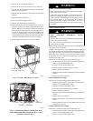
Toassure properfunctioning oftheunit,flow ofcondenserairmust
not be obstructed from reaching the unit. Clearance from the top of
the unit is 48 in. (1219 mm). Clearance of at least 36 in. (914 mm)
is required on sides except the power entry side (42 in.[1067 mm]
clearance) and the duct side (12 in. [305 mm] minimum clearance).
Maintenance and Care for the Equipment Owner
Before proceeding with those things you might want to maintain
yourself, please carefully consider the following:
FIRE,EXPLOSION,ELECTRICALSHOCKHAZARD
Failure to follow this warning could result in personalinjury,
death or property damage.
BEFORE SERVICING OR PERFORMING MAINTE-
NANCE ON YOUR UNIT:
1. TURN OFF GAS SUPPLY TO YOUR UNIT.
2. TURN OFF ELECTRICAL POWER TO YOUR UNIT.
!
WARNING
CUT HAZARD
Failure to follow this caution may result in personal injury .
When rem oving access panels or performing maintenance
functions inside yourunit,be awareofsharpsheetmetalparts
and screws. Although special care is taken to reduce sharp
edges to a minimum, be extremely careful when handling
parts or reaching into the unit.
CAUTION
!
Air Filters
The air filter(s)shouldbe checked every 3 or 4 weeksandchanged
or cleaned whenever it becomes dirty . Dirty filters produce exces-
sivestresson theblowermotorandcan causethemotor tooverheat
and shut down.
This unit must have air filters in place before it can be operated.
Thesefilters canbelocated inone of atleast two places.In many ap-
plications, the installer will provide return air f ilter grilles mounted
on thewall or ceiling ofthe conditioned structure.Intheinstanceof
filtergrilles,thefilterscan simply beremoved from the grilleandre-
placed.
The other typical application is an accessory filter rack installed in-
side the unit itself. The following information is given to assist in
changing filters used in these internal filter racks.
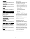
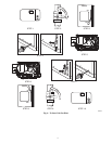
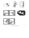
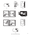
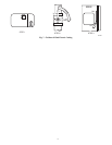
Table 1 indicates the correct filter size for your unit. Referto Fig. 2
to access f ilters installed in the accessory filter rack.
Table 1—Air Filters Located Inside Unit
(For Replacement Purposes)
Unit Size Quantity Filter Size in. (mm)
A24---A30 2
12x20x1
(305X610x25)
A36---A60 3
12x24x1
(305x610x25)
To replace or inspect filters in accessory filter rack (See Fig. 2):
1. R emove the f ilter access panel using a 5/16--in. nut driver.
2. Removethefilter(s)bypullingitoutoftheunit.Ifthefilter(s)
is dirty , clean or replace with a new one.
When installing thenew filter(s),notethedirection oftheairflowar-
rows on the filter frame.
If you have difficulty locating your air filter(s) or have questions
concerning proper filter maintenance, contact your dealer for in-
structions.When replacing filters,always usethesame sizeandtype
of filter t hat was s upplied originally by the installer.
FIRE AND UNIT OPERATIONAL HAZARD
Failure to follow this warning could result in death, personal
injury and/or property damage.
Never operate your unit without filters in place. An
accumulation of dustand linton internalpartsofyourunitcan
cause loss of efficiency.
WARNING
!