


3
UNIT INTRODUCTION
This 48XL--Aunit isasmall packaged gas heat/electric cooling sys-
tem that can utilize the comfort of gas heating packaged along with
efficient electric air conditioning. This unit uses Puron
®
, the envi-
ronmentally friendly refrigerant, for cooling.
OPERATING YOUR UNIT
Theoperation ofyour unit is controlledby theInfinityr User Inter-
face (UI). You simply program the UI and it maintains the indoor
temperature at the level you select. See UI manual for detailed in-
structions.
Tobetterprotectyour investmentand toeliminate unnecessary ser-
vice calls, familiarize yourself with the following facts:
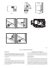
To start unit gas heat:
Refer to Fig. 2 for l ocation of unit front access panel. Refer to Fig.
3 forlocation of gasvalve. Referto Fig. 4while proceeding with the
following steps.
1. Set the temperature selector on UI to the lowesttemperature
setting and set system switch to HEAT.
2. Close the external manual gas shutoff valve.
3. Turn off the electrical supply to the unit.
4. Remove the control access panel with a 5/16--in. nut driver .
(See Fig. 3.)
5. Movetheselectorswitch ontheinternalgasvalvetotheOFF
position and wait 5 minutes.
6. Movetheselector switch on theinternalgasvalvetotheON
position.
7. Replace the c ontrol access panel.
8. Turn on the electrical supply to unit.
9. Open the external manual gas shutoff valve.
10. Set the temperatureselectoron UI slightly above roomtem-
perature to start unit. The induced --draft combustion airfan
will start. Maingasvalvewillopen andmainburnersshould
ignitewithin 5 seconds. If the burner does notlightwithin 5
seconds, theignition module willgointoaRetry Modeafter
a period of approximately 22 seconds (following the
5--second ignition period). If the burners do not light within
15 minutes of the initial call for heat, there is a lockout.
11. Set the temperature selector on UI to desired setting.
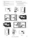
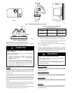
Access Panels
Filter Access Panel
For Accessory Filter Rack
A09045
Fig. 2 -- Accessory Filter Rack Access Panel
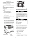
Burners
Gas Valve
Flue Hood
A09043
Fig. 3 -- Gas Heating/Electric Cooling Unit with Access Panel
Removed (Standard unit shown. Actual appearance is shown
in Fig. 2.)
FIRE AND EXPLOSION HAZARD
Failure to follow this warning could result in personalinjury,
death, and/or property damage.
1. If the main burners fail to light, or the blower fails to start,
shutdown gasheating section andcallyourdealerforservice.
2. Never attempt to manually light the main burners on unit
with a match, lighter, or any other flame. If the electric
sparking device fails to light the main burners, refer to the
following shutdownprocedures,then call yourdealerassoon
as possible.
!
WARNING
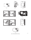
To shut off unit gas heat:
FIRE, EXPLOSION, ELECTRICAL SHOCK
HAZARD
Failure to follow this warning could result in personalinjury,
death, and/or property damage.
Do not turn off the electrical power to unit without first
turning off the gas supply.
!
WARNING
Note:If the unit is being shut down because of a malfunction, call
your dealer as soon as possible.
Shouldoverheating occurorthegassupplyfail to shut off, shutoff
the external manualgasvalvetotheunitbeforeshuttingofftheelec-
trical supply. Do not use this unit if any part has been under water.
Immediately call a qualified service technician to inspect the unit
and to replace any part of the control system and any gas control
which has been under water.
Refer to Fig. 4 while proceeding with the f ollowing steps.
1. Set thetemperatureselectoron UI to lowest temperatureset-
ting and set system SWITCH to OFF.
2. Close the external manual shutoff valve.
3. Turn off the electrical power supply to the unit.
4. Remove the control access panel.
5. Movetheselectorswitchontheinternalgasvalveto theOFF
position.
To start unit electric cooling:
Refer to Fig. 5 while proceeding with the f ollowing steps.
1. Set the temperature selector on UI to highest temperature
setting and set system SWITCH to OFF.
2. Close the external manual shutoff valve, if not already
closed.
3. Turn off the electrical power supply to the unit.