


6
Combustion Area and Vent System —
The com-
bustion area and vent system should be visually inspected
before each heating season. The normal accumulation of dirt,
soot, rust, and scale can result in loss of efficiency and improp-
er performance if allowed to build up.
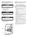
See Fig. 1A, 1B and 5 and proceed as follows to inspect the
combustion area and power-venting system of your unit.
1. Turn off gas supply to your unit.
2. Turn off electrical power to your unit.
3. Remove burner access panel.
4. Using a flashlight, carefully inspect the burner areas for
dirt, soot, or scale.
5. When you have completed your inspection, follow the
start-up procedures in this manual to restore your unit to
operation.
6. Observe unit heating operation.
Watch the burner flame to see if it is bright blue. If you
observe a suspected malfunction or that the burner flame
is not bright blue, call your dealer.
7. Replace burner access panel.
Unit Panels —
After performing any maintenance or
service on the unit, be sure all panels are securely fastened in
place to prevent rain from entering unit cabinet and to prevent
disruption of the correct unit airflow pattern.
REGULAR DEALER MAINTENANCE
In addition to the type of routine maintenance you might be
willing to perform, your unit should be inspected regularly by a
properly trained service technician. An inspection (preferably
each year, but at least every other year) should include the
following:
1. Inspection of all flue product passages — including the
burner, heat exchanger, and flue collector box.
2. Inspection of all combustion- and ventilation-air passages
and openings.
3. Close inspection of all gas pipes leading to and inside
your unit.
4. Inspection, and if required, cleaning of the condenser and
evaporator coils.
5. Inspection, and if required, cleaning of the condensate
drain pan and trap.
6. Inspection of all supply- and return-air ducts for leaks,
obstructions, and insulation integrity. Any problems
found should be resolved at the time of inspection.
7. Inspection of the unit base for cracks, gaps, etc., which
may cause a hazardous condition.
8. Inspection of the unit casing for signs of deterioration.
9. Inspection of all electrical wiring and components to en-
sure proper connection.
10. Inspection for leaks in the refrigerant circuit. Pressure-
check to determine appropriate refrigerant charge.
11. Inspection and cleaning of fan wheels and housings,
belt tension, and fan motor, shaft bearings, and pulley
alignment.
12. Operational check of the unit to determine working con-
ditions. Repair or adjustment should be made at the time
of inspection.
Your servicing dealer may offer an economical service con-
tract that covers seasonal inspections. Ask for further details.
Complete Service Instructions can be found in the unit
Installation, Start-Up and Service Instructions.
If your unit makes an unusual or especially loud noises
during heating, shut down the heating section and call your
dealer.
If dirt, soot, rust, or scale accumulations are found, call
your dealer and do not operate your heating section.
Components in heat section may be hot after unit has been
started up. When observing flame, be careful not to get to
close to or touch heating components. Serious personal
injury may result.
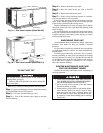
INDUCED-DRAFT
MOTOR
GAS VALVE
Fig. 5 — Typical Heat Section Detail
(Size 004-007 Shown)