


2
Step 4 — Check Unit Operation and Make
Necessary Adjustments
NOTE: Gas pressure must not be less than 5 in. wg or greater
than 13 in. wg at the unit connection.
1. Remove pressure tap plug from manifold pipe and
connect a pressure gage or manometer.
2. Turn on electrical supply.
3. Open the manual shutoff valve on the gas supply pip-
ing. Check pipe connection to main gas valve for
leaks.
4. Set the switch on the main gas valve to the ON position.
5. Call for high stage heat (W2 energized). The unit may
require several ignition attempts due to trapped air in
the manifold pipe.
6. When main burners ignite check orifice fittings for
leaks. Repair if necessary.
7. Verify that manifold pressure is between 2.7 and
3.0 in. wg while in high fire (W2 energized). Readjust
pressure if necessary.
8. Shut down unit by turning down thermostat (units with
electro-mechanical control) or putting unit in Service
Test mode (units with ComfortLink™ control), shut-
ting off manual gas valve, and shutting down power to
unit.
Never use a match or other open flame to check for leaks.
Use a soap and water solution. Fire or serious injury could
result.
If unit is equipped with a 2-stage gas valve, ensure valve
has energized second stage (high fire) before adjusting
manifold pressure. Improper manifold pressures may cause
explosion or injury.
This unit is designed to operate at 3.0 in. wg (± 0.3 in. wg)
manifold pressure at high fire. Exceeding this pressure will
cause explosion or injury.
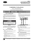
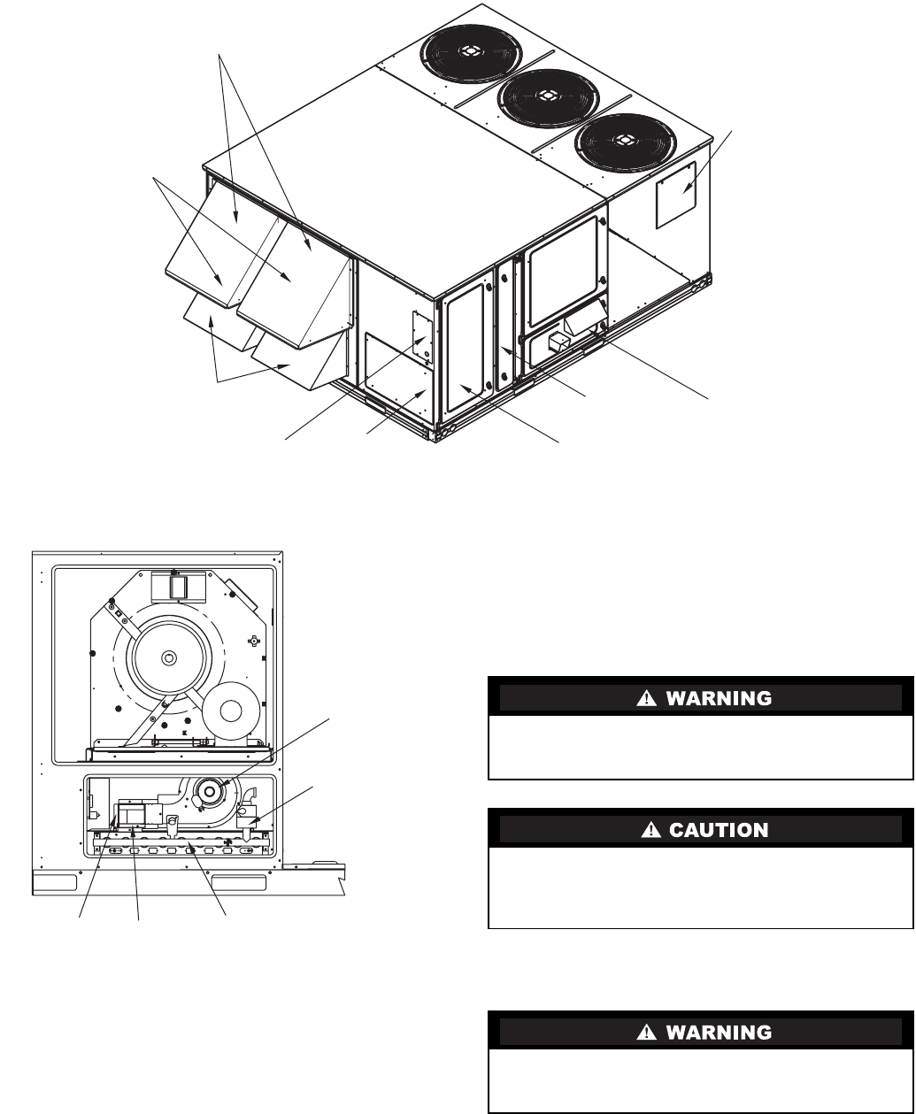
Fig. 1 — Panel and Filter Locations
CONDENSER
COIL ACCESS
PANEL
FILTER
ACCESS DOOR
CONTROL BOX
AND COMPRESSOR
ACCESS DOOR
BASEPAN
CONNECTIONS
ACCESS PANEL
BAROMETRIC
RELIEF DAMPER
HOODS
OUTDOOR AIR
SCREENS
(HIDDEN)
ECONOMIZER HOODS
ELECTRICAL
OPTIONS
PANEL
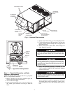
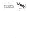
GAS SECTION
ACCESS DOOR
INDUCED
DRAFT
MOTOR
MAIN GAS
VALVE
MAIN
BURNER
SECTION
COMBUSTION
FAN HOUSING
HEAT
EXCHANGER
SECTION
Fig. 2 — Typical Gas Heating Section