


8
MAINTAINING YOUR UNIT
All maintenance should be handled by skilled, experienced
personnel. Your dealer can help you establish a standard
procedure.
For your safety, keep the area around the unit clear and free
of combustible materials, gasoline and other flammable liquids
and vapors.
To assure proper functioning of the unit, flow of combustion
and ventilating air must not be obstructed from reaching the
unit. Clearance of at least 6 ft on all sides is required.
ROUTINE MAINTENANCE AND CARE
FOR THE EQUIPMENT OWNER
Before proceeding with those things you might want to
maintain yourself, please carefully consider the following:
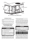
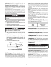
Air Filter(s) — Air filters should be checked at least
every 3 or 4 weeks and changed or cleaned whenever they
become dirty. Table 1 indicates the correct filter size for your
unit. Open the filter access panel to replace or inspect the
filters. All units have filter tracks into which the filters slide.
Remove the filters by pulling the filter slide outward from the
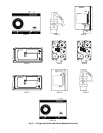
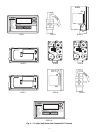
track. See Fig. 6 for filter access panel location. Note the direc-
tion of flow arrows on the filter frame.
If you have difficulty in locating your air filter in the return-
air duct system, or if you have questions concerning proper
filter maintenance, contact your dealer for instructions. When
replacing your unit filters, always use the correct size and
quantity as shown in Table 1. Filter tracks are field convertible
for 2 or 4-in. thick filters. Verify airflow and duct static values,
and related motor sizing and belt drive adjustment, if filter type
or efficiency rating is changed from the original installation.
Units with outdoor air capability have cleanable screens for
the outdoor air. These screens should be checked annually and
cleaned as necessary.
Table 1 — Indoor Air Filter Data
Alarm Status (Units with
Comfort
Link™ Con-
trol) —
The Scrolling Marquee display incorporates an
Alarm Status LED that turns on to indicate an active alarm or
alert. These alarms and alerts are in addition to those that
are indicated by the Integrated Gas Control (IGC). The
ComfortLink control active alarm codes and alarm history can
be viewed with the Scrolling Marquee or other Carrier Comfort
Network® (CCN) devices. Alarms may also be configured to
broadcast automatically on CCN. If the unit will not operate
1. TURN OFF GAS SUPPLY AND ELECTRICAL
POWER TO YOUR UNIT BEFORE SERVICING
OR PERFORMING MAINTENANCE.
2. Do not turn off electrical power to this unit without
first turning off the gas supply.
3. When opening access doors or performing mainte-
nance functions inside your unit, be aware of sharp
sheet metal parts and screws. Although special care
has been taken to reduce sharp edges to a minimum,
be extremely careful when handling parts or reaching
into the unit.
Never operate your unit without filters in place. Failure to
heed this warning may result in damage to the blower
motor and/or compressor. An accumulation of dust and lint
on internal parts of your unit can cause loss of efficiency
and in some cases, fire.
UNIT 48PG FILTER QUANTITY FILTERSIZE (in.)
03-07 4 16 x 25 x 2 or 16 x 25 x 4
08-14 6 20 x 25 x 2 or 20 x 25 x 4
16 8 20 x 20 x 2 or 20 x 20 x 4
CONTROL BOX
AND COMPRESSOR
ACCESS DOOR
OUTDOORAIR
SCREEN
FILTERACCESS
DOOR
GAS SECTION
ACCESS DOOR
INDOOR MOTOR
ACCESS DOOR
CONDENSER COIL
ACCESS DOOR
Fig. 6 — Panel and Filter Locations (48PG03-07 Shown)