


2
TO SHUT UNIT OFF
Refer to Fig. 3 while proceeding with the following steps.
Step 1 —
Set room thermostat to lowest temperature setting
and set SYSTEM switch to OFF.
Step 2 —
Close the external manual gas valve.
Step 3 —
Turn off the electrical power supply to unit;
install lockout tag.
Step 4 —
Remove the compressor access panel.
Step 5 —
Move the gas valve switch to the OFF position.
Step 6 —
Replace compressor access panel.
Step 7 —
If unit is being shut down because of a malfunc-
tion, call your dealer as soon as possible.
If unit is being shut down because the heating season has
ended, restore electrical power to the unit and set thermostat to
the COOL position to ensure operation of the cooling system
during the cooling season.
Should overheating occur, or the gas supply fail to shut off,
shut off the manual gas valve to the unit before shutting off the
electrical supply.
Do not use this unit if any part has been under water. Imme-
diately call a qualified service technician to inspect the unit and
to replace any part of the control system and gas control that
has been under water.
MAINTAINING YOUR UNIT
All maintenance should be handled by skilled, experienced
personnel. Your Carrier service technician can help you set up
a maintenance schedule.
For your safety, keep the area around the unit clear and free
of combustible materials, gasoline, and other flammable liq-
uids and vapors.
To ensure proper functioning of the unit, flow of combus-
tion and ventilating air must not be obstructed from reaching
the unit. Clearance of at least 3 ft on flue and condenser sides
and 6 in. on all other sides is required.
1. Do not turn off the electrical power to unit without
first turning off the gas supply.
2. Never attempt to manually light the main burners on
unit with a match, lighter, or any other flame. If the
electric sparking device fails to light the main burners,
refer to the following shutdown procedures. Call your
dealer as soon as possible.
Failure to follow these procedures can result in fire, seri-
ous injury or death.
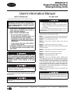
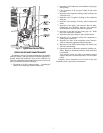
GAS VALVE
FLUE OPENING
COMPRESSOR ACCESS PANEL
INTAKE LOUVERS
Fig. 1A — Gas Valve Location
(48HJ004-007)
Fig. 1B — Gas Valve Location
(48HJ008-014)