


START UNIT
To start unit:
1. Close the unit-mounted ON/OFF switch (located in the
main control box).
2. Close the field-supplied and -installed timeclock (or con-
trol) switch (contacts located at Terminals 1 and 2 (TB3
for 034-048, TB4 for 054-104).
IMPORTANT: The field-suppliedand installed switch
(or timeclock) MUST BE CLOSED to put unit in
Occupied mode. Unit WILL NOT START until this
is accomplished.
3. Initialization mode begins (see Operating Information sec-
tion on page 34 for complete description of sequences
and display codes).
4. Run Quick Test. If the display button is pressed during
the initialization mode period, the unit will run its self-
88diagnostic routine. When this is in effect, an will ap-
pear in the display screen. Refer to Quick Test Program
section below, for instructions on completing the Quick
Test program.
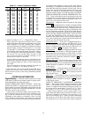
Quick Test Program — Turn on power to unit.
IMPORTANT: The field-supplied switch (or time-
clock) must be closed to put unit into the occupied mode.
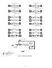
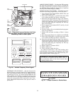
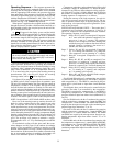
The quick test program utilizes the 2-digit LED display
(see Fig. 6) on the set point board to show status of all input
and output signals to microprocessor. Display action and quick
test procedures are described below.
The quick test program is a 33-step program that provides
a means of checking all input and output signals of controls
prior to unit start-up. This check ensures that all control op-
tions, thermistors, and control switches are in proper work-
ing order.
When unit control circuit is switched to Occupied mode,
20a will appear on the display. Immediately press display
88
button once. An will appear on the display and alarm
light on display board will be energized. This indicates that
control system is ready to run quick test program.
IMPORTANT: Do not allow unit control circuit to
20
remain energized with showing on display for more
than 2 minutes. If display button is not pressed within
this time period, control will attempt to start unit.
For each step of the 33-step program, display button must
be pressed twice. On first press, step number is displayed;
second press initiates required action and appropriate code
is displayed.
NOTE: The step number is a numeral followed by a decimal
point (a 2-digit number has a decimal point after each nu-
meral). The action code number is one or 2 digits with no
decimal point(s).
IMPORTANT: Once quick test is initiated, display but-
ton must be pressed at least once every 10 minutes for
control to remain in quick test mode. If button is not
pressed within this time, control will attempt to start
the unit.
To recheck any step in quick test program, control must
be recycled by turning unit control switch off for a few sec-
onds, and then turning it back on again. Restart quick test
program as described above and proceed through quick test
steps. Press display button twice for each step until step to
be rechecked is reached.
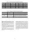
The quick test program is divided into 3 sections as de-
scribed below and shown in Tables 15-17.
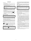
1. Quick Test Steps 1.-1.3. — Unit Configuration and Switch
Check
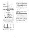
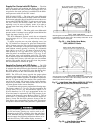
The microprocessor in unit control system is programmed
by 2 switch assemblies located on processor board
(Fig. 1). The configuration header is factory set and can-
not be changed in the field. The DIPswitch assembly con-
tains 8 microswitches that must be set in accordance with
the various options selected by the customer. All DIP
switches should be checked and set to proper position for
options selected prior to the quick test. See Configuration
of Header and DIP Switch Assembly section on page 5
for factory switch settings. The DIP switch functions and
display codes are shown in Table 15.
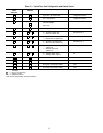
2. Quick Test Steps 1.4.-2.3. — Thermistor and Set Point
Potentiometer Check
In these steps, the microprocessor checks resistance val-
ues of all sensors and set point potentiometers to ensure
that they are functional, connected properly, and set within
proper range for unit configuration.
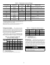
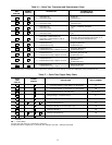
Nominal resistance valuesfor all sensors range from 363,000
to 219 ohms in accordance with Table 18. Normal dis-
play code for good sensors and potentiometers is 1.Adis-
play code of 0 indicates a faulty potentiometer, thermistor
or wiring. A 0 display also indicates that option is not
being used.
Table 16 shows thermistor and set point potentiometer
functions and quick test display codes.
31