


89
If a Y2 (or Y2_SPT) call begins while the unit was under
“Y1 cooling” control, compressor no. 2 will not be started until
“Y1 cooling” control has ended.
If the Y2 (or Y2_SPT) call ends, with compressor 1 in an
unloaded state and compressor 2 ON, then compressor 1 will
be immediately brought up to the fully loaded state. If however,
the Y2 (or Y2_SPT) call ends, with compressor 1 in an unload-
ed state and compressor 2 OFF, then compressor 1 will be left
in its unloaded state. In either case the compressor 1 will be
loaded/unloaded as appropriate to the “Y1 Low Limit”.
The control shall lockout compressors if SAT becomes too
low and an alarm shall be issued.
Compressor no. 1 lockout at SAT < 53 F.
Compressor no. 2 lockout at SAT < 48 F.
If SAT sensor fails the control will energize compressor
no. 1 fully loaded (unloaders off), whenever there is a Y1 (or
Y1_SPT) call. Compressor no. 2 will be energized whenever
there is a call for Y2 (or Y2_SPT).
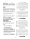
NOTE: When a VAV unit with software version 4.0 and later is
configured to operate from a space thermostat (VVT® relay
pack) or a space sensor, compressors start loaded and then
unload as needed. This is the opposite of the normal VAV
unloading sequence. When operating from supply-air tempera-
ture (SAT) sensor, VAV units will unload in the reverse
sequence.
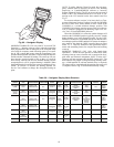
FIELD TEST — The field test program is initiated by moving
up DIP switch no. 4 to the OPEN position. The outdoor-air
damper will close. The control allows 90 seconds for the damp-
er to close in case it was in the full open position. Next, the
indoor-fan contactor will be energized, and the outside-air
damper will begin to open to its default value of 20% and stay
at that position for a short period of time. The outdoor-air
damper will then open to its full open position and stay at that
position for a short period of time. The outdoor-air damper will
then close.
If the unit is equipped with power exhaust, stage 1 will be
energized for 5 seconds. If the unit is configured for stage 2 of
power exhaust, stage 2 will be energized for 5 seconds after the
first stage is deenergized.
The first stage of heat will be energized for 30 seconds, after
which the second stage heat will be energized for an additional
30 seconds. Heat is then deenergized.
The last step is the Cooling mode. Outdoor-fan contactor
no. 1 is energized. This is followed by each stage of cooling
energized with a 10-second delay between stages. After this
is complete, outdoor-fan contactor no. 2 is energized for
10 seconds.
The compressors will now deenergize, followed by the out-
door-fan contactors and indoor-fan contactors. If the unit is
equipped with the Integrated Gas Control (IGC) board, the in-
door fan will continue to operate for an additional 30 seconds
after deenergizing the circuit.
The field test is then complete.
SERVICE
Service Access —
All unit components can be reached
through clearly labelled hinged access doors. These doors are
not equipped with tiebacks, so if heavy duty servicing is need-
ed, either remove them or prop them open to prevent accidental
closure.
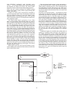
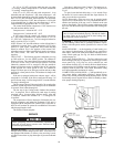
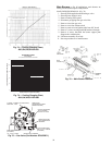
Each door is held closed with 3 latches. The latches are se-
cured to the unit with a single
1
/
4
-in. - 20 x
1
/
2
-in. long bolt. See
Fig. 63.
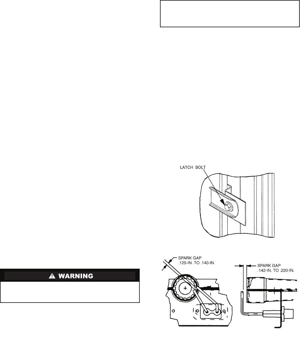
To open, loosen the latch bolt using a
7
/
16
-in. wrench. Pivot
the latch so it is not in contact with the door. Open the door. To
shut, reverse the above procedure.
NOTE: Disassembly of the top cover may be required under
special service circumstances. It is very important that the ori-
entation and position of the top cover be marked on the unit
prior to disassembly. This will allow proper replacement of the
top cover onto the unit and prevent rainwater from leaking into
the unit.
Cleaning — Inspect unit interior at beginning of each heat-
ing and cooling season and as operating conditions require.
Remove unit side panels and/or open doors for access to unit
interior.
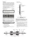
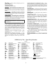
MAIN BURNERS — At the beginning of each heating sea-
son, inspect for deterioration or blockage due to corrosion or
other causes. Observe the main burner flames and adjust if nec-
essary. Check spark gap. See Fig. 64. Refer to Main Burners
section on page 94.
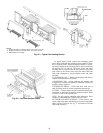
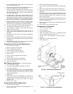
FLUE GAS PASSAGEWAYS — The flue collector box and
heat exchanger cells may be inspected by removing gas section
access panel (Fig. 5-16), flue box cover, collector box, and
main burner assembly (Fig. 65 and 66). Refer to Main Burners
section on page 94 for burner removal sequence. If cleaning is
required, clean all parts with a wire brush. Reassemble using
new high-temperature insulation for sealing.
COMBUSTION-AIR BLOWER — Clean periodically to as-
sure proper airflow and heating efficiency. Inspect blower
wheel every fall and periodically during heating season. For the
first heating season, inspect blower wheel bi-monthly to deter-
mine proper cleaning frequency.
Before performing service or maintenance operations on
unit, turn off main power switch to unit. Electrical shock
could cause personal injury.
IMPORTANT: After servicing is completed, make sure
door is closed and relatched properly, and that the latches
are tight. Failure to do so can result in water leakage into
the evaporator section of the unit.
Fig. 63 — Door Latch
Fig. 64 — Spark Gap Adjustment