


50
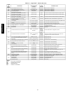
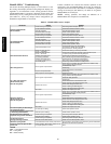
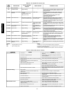
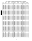
Table 18 – IGC Board LED Alarm Codes
LED
FLASH
CODE
DESCRIPTION
ACTION TAKEN BY
CONTROL
RESET METHOD PROBABLE CAUSE
On Normal Operation
— — —
Off Hardware Failure No gas heating.
—
Loss of power to the IGC. Check 5 amp fuse on IGC,
power to unit, 24V circuit breaker, transformer, and
wiring to the IGC.
1 Flash Indoor Fan On/Off Delay
Modified
5 seconds subtracted from
On delay.
5 seconds added to Off
delay (3 min max).
Power reset. High temperature limit switch opens during heat
exchanger warm‐up period before fan‐on delay
expires.
High temperature limit switch opens within
10 minutes of heat call (W) Off.
See Limit Switch Fault.
2 Flashes Limit Switch Fault Gas valve and igniter Off.
Indoor fan and inducer On.
Limit switch closed, or
heat call (W) Off.
High temperature limit switch is open. Check the
operation of the indoor (evaporator) fan motor.
Ensure that the supply‐air temperature rise is within
the range on the unit nameplate. Check wiring and
limit switch operation.
3 Flashes Flame Sense Fault Indoor fan and inducer On. Flame sense normal.
Power reset for LED
reset.
The IGC sensed a flame when the gas valve should
be closed. Check wiring, flame sensor, and gas valve
operation.
4 Flashes Four Consecutive Limit
Switch Fault
No gas heating. Heat call (W) Off.
Power reset for LED
reset.
4 consecutive limit switch faults within a single call for
heat. See Limit Switch Fault.
5 Flashes Ignition Fault No gas heating. Heat call (W) Off.
Power reset for LED
reset.
Unit unsuccessfully attempted ignition for 15 minutes.
Check igniter and flame sensor electrode spacing, gaps,
etc. Check flame sense and igniter wiring. Check gas
valve operation and gas supply.
6 Flashes Induced Draft Motor
Fault
If heat off: no gas heating.
If heat on: gas valve Off
and inducer On.
Inducer sense normal, or
heat call (W) Off.
Inducer sense On when heat call Off, or inducer
sense Off when heat call On. Check wiring, voltage,
and operation of IGC motor. Check speed sensor
wiring to IGC.
7 Flashes Rollout Switch Lockout Gas valve and igniter Off.
Indoor fan and inducer On.
Power reset. Rollout switch has opened. Check gas valve
operation. Check induced‐draft blower wheel is
properly secured to motor shaft.
8 Flashes Internal Control Lockout No gas heating. Power reset. IGC has sensed internal hardware or software error. If
fault is not cleared by resetting 24 v power, replace
the IGC.
9 Flashes Temporary Software
Lockout
No gas heating. 1 hour auto reset, or
power reset.
Electrical interference is disrupting the IGC software.
LEGEND
IGC - Integrated Gas Unit Control
LED - Light-Emitting Diode
NOTES:
1. There is a 3-second pause between alarm code displays.
2. If more than one alarm code exists, all applicable alarm codes will be
displayed in numerical sequence.
3. Alarm codes on the IGC will be lost if power to the unit is interrupted.
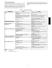
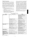
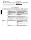
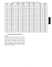
Table 19 – Electric Heat Service Analysis
PROBLEM CAUSE REMEDY
Heat Will Not Turn On.
Active alarm. Check active alarms using ComfortLink Scrolling
Marquee.
Unit is NOT configured for heat. Check heating configurations using the ComfortLink
Scrolling Marquee
No power to unit. Check power supply, fuses, wiring, and circuit breakers.
Unit is in minimum heat off‐time, or minimum cool‐heat
changeover time.
Check using ComfortLink Scrolling Marquee.
Thermostat or occupancy schedule setpoint not
calling for heating.
Check using ComfortLink Scrolling Marquee.
Heat forced off in Service Test mode. Check using ComfortLink Scrolling Marquee. Turn Service
Test mode off.
No 24 vac at heater contactor.
Check transformer and circuit breaker.
Check auto‐reset limit switches on heater.
Check manual‐reset limit switch (LS) on indoor fan housing.
Open temperature limit switch on heater. Check minimum airflow. Check limit switch when it is cool,
replace if open.
Inadequate Heating.
Dirty air filters. Replace air filters.
Thermostat or occupancy schedule setpoint only
calling for W1.
Allow time for W2 to energize or adjust setpoints.
Heat undersized for load. Decrease load or increase size of heater.
Restricted airflow Remove restriction. Check SAT compared to the SAT
heating limits.
Too much outdoor air. Check economizer position and configuration. Adjust
minimum position.
Limit switch cycles heaters. Check rotation of blower and minimum airflow.
Bad heater elements. Power off unit and remove high voltage wires. Check
resistance of element, replace if open.
Heat Will Not Turn Off.
Unit is in minimum heat on‐time. Check using ComfortLink Scrolling Marquee.
Thermostat or occupancy schedule setpoint still
calling for heating.
Check using ComfortLink Scrolling Marquee.
Heat forced on in Service Test mode. Check using ComfortLink Scrolling Marquee. Turn Service
Test mode off.
Heater contactor failed. Power off unit. Check contactor and replace if closed.
48/50PG and PM