


Manufacturer reserves the right to discontinue, or change at any time, specifications or designs without notice and without incurring obligations.
Catalog No. 04-53480064-01 Printed in U.S.A. Form 48/50-73SI Pg 4 8-09 Replaces: 48/50A-4SI
Copyright 2009 Carrier Corporation
START-UP
After applying power, the CO
2
sensor will enter a warm-up
mode. Warm-up duration will be from 1 to 10 minutes. The
warm-up duration will be shorter in warmer temperatures and
longer in cooler temperatures. During warm-up, the signal
output will be 4 mA. Once the unit has warmed up, the voltage
or current output will be set up to indicate the CO
2
level. The
display will show a steady reading 1 minute later.
Configuring the ComfortLink™ Controller —
The CO
2
sensor is defaulted to provide 4 mA at 0 ppm and
20 mA at 2000 ppm. If a different range is necessary, contact
Carrier Application Engineering to reconfigure the sensor. If
the sensor is reconfigured, the mA range on the ComfortLink
controller must be configured to match the new values. Refer
to Controls and Troubleshooting Guide for configuration
details.
Sensor Self Calibration — The CO
2
sensors employ a
self-calibration system. The system eliminates the need for
manual calibration in applications where the indoor CO
2
level
drops to outside levels during unoccupied periods (e.g., during
evening hours). A special software routine in the sensor re-
members the background readings for 14 consecutive eve-
nings, calculates if there is a sensor drift, and then corrects for
it.
NOTE: This only applies when used in typical indoor or ambi-
ent air conditions. Consult Carrier application engineering if
other gases or corrosive agents are part of the application
environment.
SERVICE
Cleaning —
The controller is a rugged and lightweight unit
that requires very little maintenance. Clean external surfaces
periodically with a dampened cloth.
TROUBLESHOOTING
The following occurrences may indicate abnormal opera-
tion, caused primarily by power input fluctuations, surges, or
spikes.
• The unit remains in warm-up mode for more than
10 minutes.
• The LED glows with no pulse.
•CO
2
indication (display numbers or signal output) is
frozen.
• Numbers on the display change continuously for longer
than 1 minute.
Normal operation can usually be restored by removing
power, shutting down the unit for at least 15 seconds, then
reconnecting power. The unit should warm up, as described
above, then return to normal operation. If the situation
continues, remove and replace the sensor.
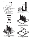
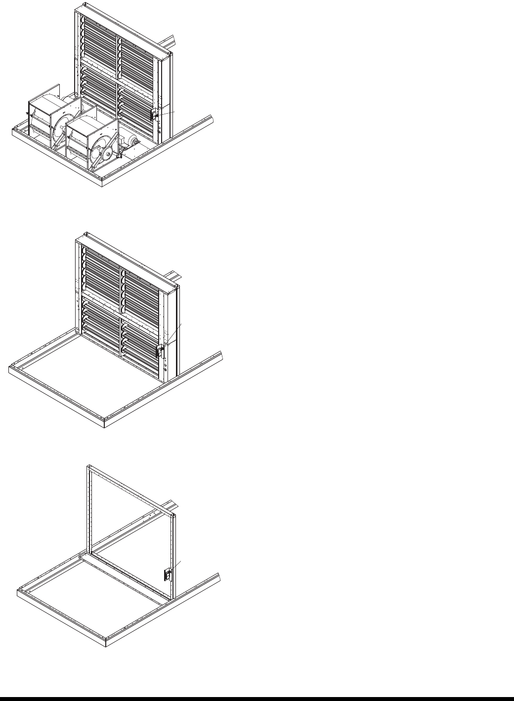
CO
2
SENSOR
AND BRACKET
CO
2
SENSOR
AND BRACKET
Fig. 10 — CO
2
Bracket for 48/50P055-100 and
48/50Z055-105 Units (Economizer Only)
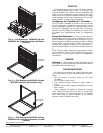
Fig. 11 — CO
2
Bracket for 48/50P055-100 and
48/50Z055-105 Units (No Economizer or Power
Exhaust)
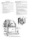
Fig. 9 — CO
2
Bracket for 48/50P055-100 and
48/50Z055-105 Units (Economizer with Power
Exhaust)
CO
2
SENSOR
AND BRACKET