


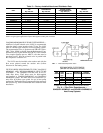
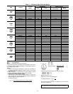
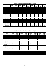
Table 6 — Fan Contactor Coil Data
UNIT
40RM, 40RMQ
40RMS
VOLTAGE
(vac)
MAXIMUM
HOLDING
VA
007-034 24 10
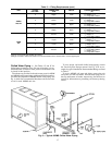
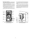
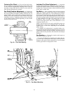
Connecting Ductwork — Refer to the Carrier Sys-
tem Design Manual for the recommended design and layout
of ductwork. Figure 15 shows recommended duct connec-
tion to units with 2 fans.
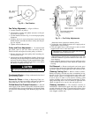
DISCHARGE CONNECTIONS — Duct flanges are factory
supplied; they are shipped inside the unit attached to the hair-
pin end of the coil tube sheet for field installation. Using the
existing screws, install the duct flanges on the unit’s fan deck.
Each fan discharge requires 2 flanges; each flange must be
bent in the middle to conform to the discharge opening. See
Fig. 16. After flanges are installed, connect them to the sup-
ply duct using a canvas connection to prevent vibration. It is
important that this connection be properly fabricated to pre-
vent high air friction losses and air noise.
RETURN CONNECTION — When using return-air duct-
work, route return-air duct to the unit’s return air inlet near
the filter rack, using a canvas connection to prevent trans-
mission of unit vibration. If the duct blocks off the unit’s
access panel, provide a slip joint in the ductwork to permit
removal for servicing.
OUTDOOR-AIR INLET CONNECTION — Connect outdoor-
air inlet to field-installed accessory economizer. Refer to econo-
mizer Installation Instructions.
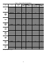
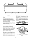
Return-Air Filters — Type and size of filters are
shown in Tables 1A-1F and are factory-supplied and in-
stalled. In all units with 2 fans, a filter replacement tool (hook)
is shipped inside the unit for field use when replacing filters.
See the Service section for instructions on filter element
replacement.
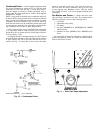
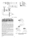
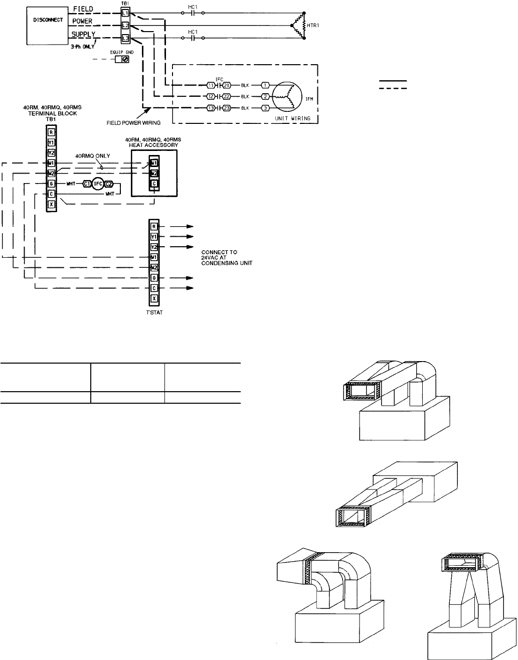
Fig. 14 — Unit Wiring
LEGEND
CB — Circuit Breaker
HC — Heating Contactor
HTR — Electric Heater
IFC — Indoor-Fan Contactor
IFM — Indoor-Fan Motor
NEC — National Electrical Code
TB — Terminal Block
T’STAT — Thermostat
Factory Wiring
Field Control Wiring
NOTE: Use copper conductors only.
Fig. 15 — Typical Fan Discharge Connections
for Multiple Fan Units
596 22
→