


NOTE: A backup wrench on the hex part of the suction valve
fitting is required while tightening.
The tube end must stay bottomed in the service valve during
final assembly to ensure proper seating, sealing, and rigidity.
MECHANICAL FITTING REPAIR
To replace damaged ferrule or tubing, proceed as follows.
1. Attach gages to service valves.
2. Close liquid service valve and operate unit in cooling mode to
pump refrigerant charge into condenser coil.
3. When suction pressure reaches 5 psig, shut unit off. Do not
operate unit in a vacuum.
4. Close suction service valve and recover refrigerant in tubing.
5. Back-off locknut and ferrule onto tube.
6. Remove damaged part of tubing using tubing cutter. Repeat
installation procedure previously outlined using new ferrule.
7. Evacuate tubing set and indoor coil. Check for leaks.
8. Open service valves or recharge unit. Check refrigerant
charge.
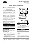
Fig. 2—Refrigerant Tube Dimensions/Connections
UNIT SIZE
LIQUID TUBE VAPOR TUBE
Conn Dia Tube Dia Conn Dia Tube Dia
018, 024 3/8 3/8 5/8 5/8
030, 036 3/8 3/8 3/4 3/4
042, 048 3/8 3/8 7/8 7/8
060 3/8 3/8 7/8 1-1/8
Tube diameters are for lengths up to 50 ft. For tubing lengths greater than 50
ft, consult your local distributor.
A93578
LIQUID LINE CONN
FIELD CONTROL
SUPPLY CONN
7
⁄
8
″ DIA HOLE
FIELD POWER
SUPPLY CONN
7
⁄
8
″ DIA HOLE WITH
1
1
⁄
8
″ DIA KNOCKOUT
AND
1
3
⁄
8
″ DIA
KNOCKOUT
AIR DISCHARGE
SUCTION LINE CONN
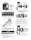
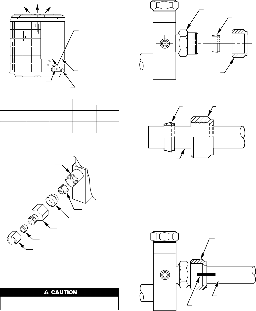
Fig. 3—Liquid Service Valve Mechanical Fitting
Assembly (38YCP Model)
A94030
PISTON BODY
PISTON
PISTON RETAINER
LOCK NUT
LIQUID SERVICE
VALVE ADAPTER
FERRULE
Fig. 4—Suction Service Valve with Mechanical
Adapter (38YCP Model)
A92120
VALVE FITTING
FERRULE
LOCK NUT
Fig. 5—Lock Nut/Ferrule Positioning
A92121
FERRULE LOCK NUT
TUBING
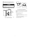
Fig. 6—Proper Marking of Valve Assembly
A92122
LOCK NUT
MARK ON LOCK NUT
AND TUBE
TUBING
2