


GB - 11
38VYX050/38VYX080
ENGLISH
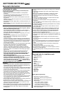
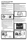
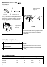
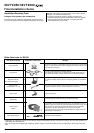
Final installation checks
Check and Test Operation
For R410A, use the leak detector exclusively manufactured for HFC
refrigerant (R410A, R134a, etc.).
• The conventional leak detector for HCFC refrigerant (R22, etc.)
cannot be used because its sensitivity for HFC refrigerant lowers
to approx. 1/40.
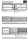
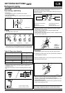
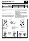
ቢ Piping cover
ባ Check points
of outdoor unit
ቤ Flare nut
connections
(Indoor unit)
ብ Valve cover
ባ
ቢ
ብ
ቤ
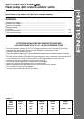
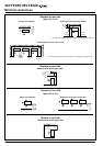
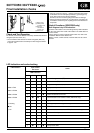
LED indication Cycle control
Cause
P.C. board
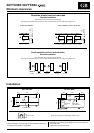
LED indication
D800 D801 D802 D803
ȚȜ ȜȜHeat exchanger sensor (TE) error
ȜȜ ȚȜSuction sensor (TS) error
ȚȚ ȜȜHot gas discharge sensor (TD) error
D800 O: Red ȜȚ ȜȚHigh-pressure protection error
D801 O: Yellow ȜȚ ȜȜOutdoor air temperature sensor error (TO)
D802 O: Yellow ȚȚ ȚȜOutdoor motorised fan error DC
D803 O: Yellow ȚȜ ȜȚCommunication error between IPDU (Abnormal stop)
ȜȚ ȜȚHigh-pressure release operation
«: Flashing ȜȚ ȚȜDischarge temp. error: hot gas is too high
Ȝ: Off ȚȚ ȜȚEEPROM error
Ț: On ȜȜ ȚȚCommunication error between IPDU (No abnormal stop)
«Ȝ ȜȜG-Tr short-circuit protection
Ȝ« ȜȜDetect circuit error
«« ȜȜCurrent sensor error
ȜȜ «ȜComp. lock error
«Ȝ «ȜComp. break down
LED indication and code checking
• Pressure of R410A is approx. 1.6 times higher than that of R22.
If installation work is incompletely finished, a gas leakage may
occur when pressure rises during operation.
Therefore, be sure to test the piping connections for leakage.
• Check gas leakage at the flare nut connections, valve stem cap
connections and service port cap fittings with a leak detector or
soap water.
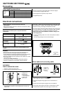
Useful Functions (38VYX080 only)
Self-Diagnosis by LED Indication
Troubles of the outdoor unit can be diagnosed by LED indications
on the cycle control P.C. board of the outdoor unit. Utilize them for
various checks.
For the check by remote controller of the indoor unit, refer to the
Installation Manual of the outdoor unit.
Before a check, confirm each bit of the DIP switch is set to OFF
position.