


21
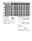
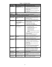
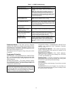
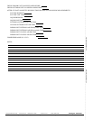
Table 7 — CADM Troubleshooting
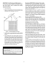
Crankcase Heater — The heater prevents refrigerant
migration and compressor oil dilution during shutdown when-
ever compressor is not operating. The heater is wired to cycle
with the compressor; the heater is off when compressor is run-
ning, and on when compressor is off.
The crankcase heater will operate as long as the power circuit
is energized.
Compressor Protection
COMPRESSOR OVERTEMPERATURE PROTECTION
(IP) — A thermostat installed on the compressor motor wind-
ing reacts to excessively high winding temperatures and shuts
off the compressor.
CRANKCASE HEATER — The heater minimizes absorp-
tion of liquid refrigerant by oil in the crankcase during brief or
extended shutdown periods. The main disconnect must be on
to energize the crankcase heater.
ADVANCED SCROLL TEMPERATURE PROTECTION
(ASTP) — See “Advanced Scroll Temperature Protection
(ASTP)” on page 15.
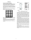
Low-Pressure Switch — The 38AUZ low-pressure
switch is stem-mounted on the suction line. Switches are all
fixed, non-adjustable type.
High-Pressure Switch — The 38AUZ high-pres-
sure switch is stem-mounted on the discharge line. The switch
is a fixed, non-adjustable type.
Outdoor Fans — Each fan is supported by a formed-wire
mount bolted to the fan deck and covered with a wire guard.
Fan motors have permanently lubricated bearings.
Lubrication
FAN MOTORS have sealed bearings. No provisions are made
for lubrication.
COMPRESSOR has its own oil supply. Loss of oil due to a
leak in the system should be the only reason for adding oil after
the system has been in operation.
Miswired Module Indication Recommended Troubleshooting Action
Green LED is not on,
module does not power up
Determine if both R and C module terminals are
connected. Verify voltage in present at module’s R and C
terminals.
NOTE: The CADM requires a constant nominal 24VAC
power supply. The wiring to the module’s R and C
terminals must be directly from the control transformer.
The module cannot receive its power from another device
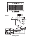
that will interrupt the 24VAC power supply. See Fig. 20,
the 38AU Wiring Diagram.
Green LED Intermittent,
module powers up only
when compressor runs
Determine if R and Y terminals are wired in reverse. Verify
module’s R and C terminals have a constant source. See
“NOTE” above for details on R and C wiring.
TRIP LED is on but system
and compressor check OK
Verify Y terminal is wired properly per the 38AU wiring
diagram (see Fig. 19). Verify voltage at contactor coil falls
below 0.5VAC when off. Verify 24VAQC is present across
Y and C when thermostat demand signal is present. If not,
R and C are reverse wired.
TRIP LED and ALERT LED
flashing together
Verify R and C terminals are supplied with 19-28VAC.
ALERT Flash Code 3
(Compressor Short Cycling)
displayed incorrectly
Verify Y terminal is connected to 24VAC at contactor coil.
Verify voltage at contactor coil falls below 0.5VAC when
off.
ALERT Flash Code 5 or 6
(Open Circuit, Missing Phase)
displayed incorrectly
Check that compressor T1 and T3 wires are through
module’s current sensing holes. Verify Y terminal is
connected to 24VAC at contactor coil. Verify voltage at
contactor coil falls below 0.5VAC when off.
Alert Flash Code *
(Welded Contactor)
displayed incorrectly
Determine if module’s Y terminal is connected. Verify Y
terminal is connected to 24VAC at contactor coil. Verify
24VAC is present across Y and C when thermostat
demand signal is present. If not, R and C are reverse
wired. Verify voltage at contactor coil falls below 0.5VAC
when off.
IMPORTANT: Never open any switch or disconnect that
energizes the crankcase heater unless unit is being serviced
or is to be shut down for a prolonged period. After a pro-
longed shutdown on a service job, energize the crankcase
heater for 24 hours before starting the compressor.