


Manufacturer reserves the right to discontinue, or change at any time, specifications or designs without notice and without incurring obligations.
Catalog No. 04-53380009-01 Printed in U.S.A. Form 38AP-5SI Pg 4 5-10 Replaces: New
Copyright 2010 Carrier Corporation
a38-7099_gs
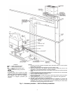
NOTES:
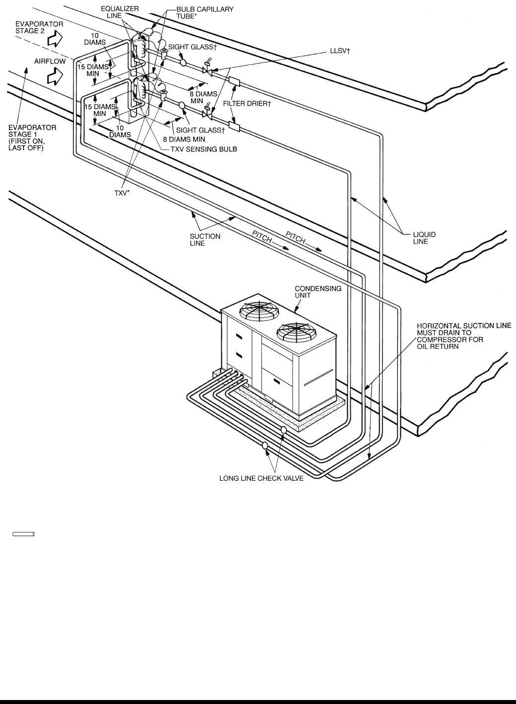
1. All piping must follow standard refrigerant piping techniques. Refer to Carrier System
Design Manual for details.
2. All wiring must comply with the applicable local and national codes.
3. Wiring and piping shown are general points-of-connection guides only and are not
intended for, or to include all details for, a specific installation.
4. Install field-supplied disconnect switch in accordance with all local and national electrical
codes.
5. Liquid line solenoid valves (solenoid drop control) are not required but are recom-
mended to prevent refrigerant migration to the compressor.
6. Factory-supplied accumulator not shown.
7. Dual-circuit piping shown. Single-circuit piping is similar but would only have one suction
line and one liquid line.
8. A field-supplied (min. 5% up to 15%) bleed port TXV is required for every application.
9. Sight glass, LLSV, and filter drier are field supplied.
10.Long line length check valves are required for liquid line installation on all linear line
length applications of more than 100 ft (30.5 m). For any 025-030 size dual-circuit unit
application where evaporator is located higher than the condensing unit, check valves
are required for linear line length above 55 ft (16.8 m).
LEGEND
*Field supplied.
†Field supplied. See base unit installation
instructions for refrigerant specialties part
numbers.
LLSV — Liquid Line Solenoid Valve
NEC — National Electrical Code
TXV — Thermostatic Expansion Valve
Piping
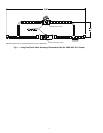
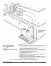
Fig. 3 — Accessory Location — 38AP Unit Ground Level Installation