


Manufacturer reserves the right to discontinue, or change at any time, specifications or designs without notice and without incurring obligations.
PC 111 Catalog No. 533-00067 Printed in U.S.A. Form 30GT/38AKS-1SI Pg 4 1-05 Replaces: 30GT-35SI
Book124
Tab 3a 5c 2a
Copyright 2005 Carrier Corporation
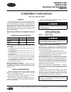
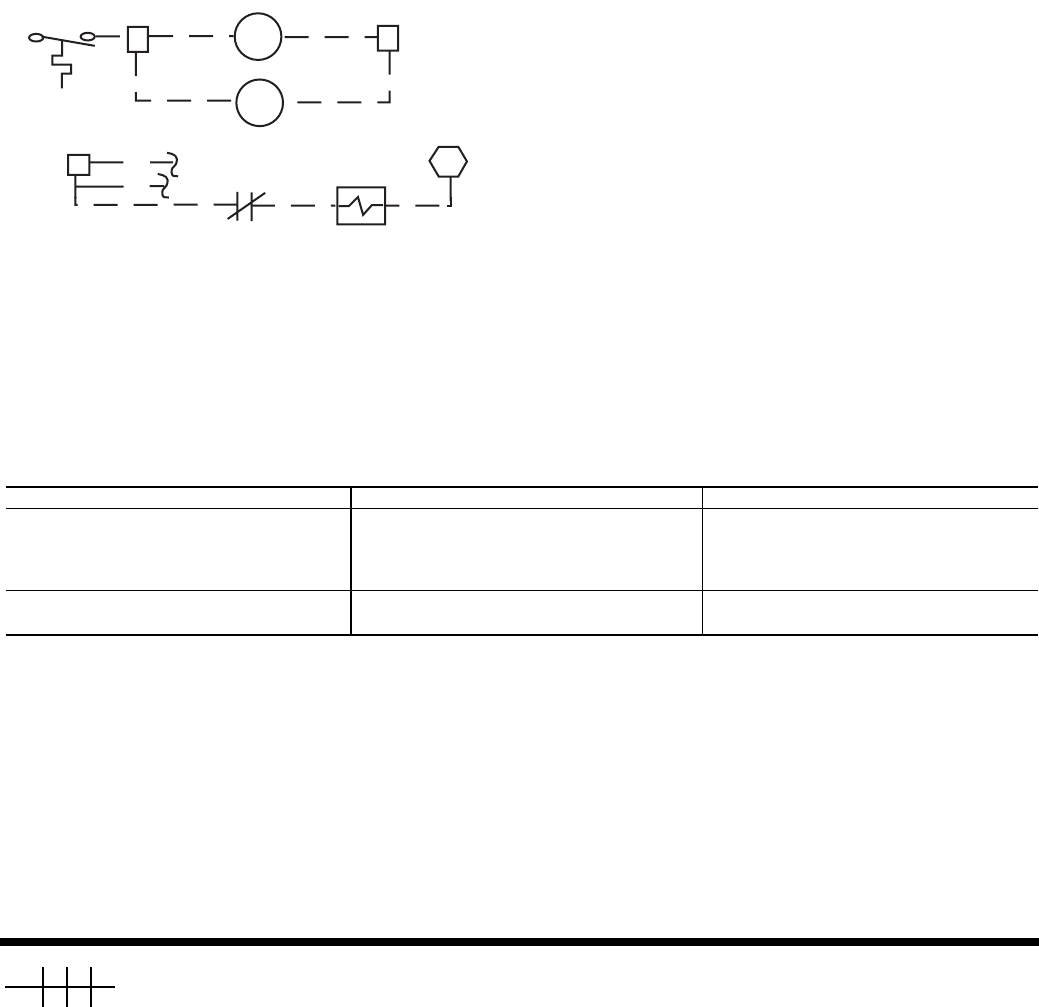
Step 2 — Install Control Wiring (See Fig. 5)
1. Install a field-supplied relay with a 24-v coil and normal-
ly closed contacts rated for 20 va at 125 vac inductive
load. Mount this relay in the 38AKS control box.
NOTE: This relay is identified in Fig. 5 as HGR (hot gas
relay).
2. For 38AKS014-024:
a. Connect a field-supplied wire between TB2-3 and
the L1 side of the HGR coil.
b. Connect a field-supplied wire between TB2-9 and
the L2 side of the HGR coil.
c. Connect a field-supplied wire between TB2-2 and
HGR-4, one of the normally closed (NC) contacts.
d. Connect one leg of the hot gas pilot solenoid valve
to HGR-6, the other NC contact.
e. Connect the other leg of the hot gas pilot solenoid
valve to C2.
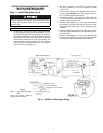
Step 3 — Restore Refrigerant Charge — Charge
unit in accordance with 38AKS Charging Chart found on unit.
ACCESSORY OPERATION AND
ADJUSTMENT
Adjustment — The hot gas bypass valve is set to begin
opening when the suction pressure falls to approximately
62 psig (427 kPa). The pressure corresponds to a chilled water
set point of approximately 44 F (6 C). If the chilled water set
point is lower than 44 F (6 C), the bypass setting must be de-
creased. The opposite is true if the chilled water setting is
above 44 F (6 C).
Condensing temperature also affects the setting of the bypass
valve, and a change may be required. To adjust the setting of the
bypass valve, a
5
/
16
in. hex wrench is required. Remove the cap
on the valve, and turn the adjustment nut with the hex wrench.
Turning in a clockwise direction increases the setting, and turn-
ing in a counterclockwise direction decreases the setting.
Operation — The hot gas bypass accessory operates as fol-
lows: When a call for cooling is received, the compressor start
circuit is energized, along with the hot gas solenoid (HGS) and
all unloaders. Once the HGS circuit is completed, the solenoid
valve opens allowing the hot gas bypass valve (HGBV) to
sense suction pressure and respond accordingly.
If the suction pressure is below the HGBP (hot gas bypass)
valve setting, the valve begins to open. The valve continues to
open until it either reaches an equilibrium or the maximum
open position. Discharge gas is bypassed into the mixed-phase
line between the expansion valve and the cooler. This condition
continues until the suction pressure rises above the HGBP
valve setting, a second stage of temperature control is called
for, or the unit cycles off.
TROUBLESHOOTING
PROBLEM PROBABLE CAUSE SOLUTION
Hot Gas Bypass Valve Fails to Open. 1. Dirt or foreign material in valve.
2. Equalizer passageway clogged.
3. External equalizer not connected or
equalizer line is pinched shut.
1. Disassemble and clean valve.
2. Disassemble and clean valve.
3. Connect or replace equalizer line.
Check solenoid valve.
Hot Gas Bypass Valve Fails to Close. 1. Dirt or foreign material in valve.
2. Diaphragm failure.
1. Disassemble and clean valve.
2. Replace element only.
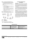
TC2
TB2
TB2
LLS
HGR
HGR
3
9
Hot Gas
BLU
YEL
C2
TB2
Pilot Solenoid Valve
LEGEND
NOTE: Hot Gas Relay (HGR) use Part No. HN61KK324.
HGR — Hot Gas Relay
LLS — Liquid Line Solenoid
TB — Ter m i na l B lo ck
TC — Thermostat Cooling
Fig. 5 — 38AKS014-024 Hot Gas Bypass Wiring