


Discharge Muffler
Installation Instructions
Part No. 324423-751 and 324424-751
NOTE: Read the entire instruction manual before starting the
installation.
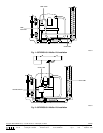
SAFETY CONSIDERATIONS
Installing and servicing air conditioning equipment can be hazard-
ous due to system pressure and electrical components. Only trained
personnel should install or service air conditioning equipment.
Untrained personnel can perform basic maintenance functions,
such as cleaning coils and cleaning and replacing filters. All other
operations should be performed by trained service personnel.
When working on air conditioner equipment, observe precautions
in the literature, on tags, and on labels attached to unit.
Follow all safety codes. Wear safety glasses and work gloves. Use
a quenching cloth for brazing operations. Have a fire extinguisher
available.
Before beginning the installation or modification, be sure the
main electrical disconnect switch is in the OFF position.
Electrical shock can cause personal injury or death.
INTRODUCTION
This instruction covers installation of a discharge muffler kit. The
discharge muffler is designed to reduce or alleviate noise trans-
mission through connecting tubing. The objectionable noise can be
caused by discharge gas pulsations.
DESCRIPTION AND USAGE
The discharge muffler kit contains a discharge muffler, preformed
copper tubes, and Installation Instructions. Refer to Table 1 for kit
contents and appropriate figure for installation on specific models.
INSTALLATION
Follow all common service practices in addition to the instructions
below when installing this kit.
Do not use torch to remove components. Oil may catch fire.
Use tubing cutters. Refer to service instructions.
Do not vent refrigerant to atmosphere. Recover during system
repair or final unit disposal. Use all service ports.
1. Turn off power and reclaim refrigerant in system.
2. Remove access panel and right corner post.
3. Cut discharge tube between compressor and condenser coil.
4. Unbraze stubs from compressor and condenser coil. Use wet
cloth around condenser coil tube to prevent overheating.
Avoid overheating as damage to components could occur.
5. Install muffler kit as shown in Fig. 1 or 2.
6. Leak check, evacuate, charge, and start system.
Table 1—Kit Contents and Figure Reference Numbers
PART NO. PART NAME PART NO. USED WITH FIG. NO.
321787-751
Muffler LM10KH001
38TKB024-311 1Copper Tubes
324659-201
324660-301
Installation Instructions 38TKB-4SI
321787-752
Muffler LM10KH015
38TKB030-311 2Copper Tubes
324662-201
324661-301
Installation Instructions 38TKB-4SI
Visit www.carrier.com
Manufacturer reserves the right to discontinue, or change at any time, specifications or designs without notice and without incurring obligations.
Book 1 2 4
Tab 3a 1a 2a
PC 101 Catalog No. 533-899 Printed in U.S.A. Form 38TKB-4SI Pg 1 1-98 Replaces: New